1. Introduction
If you’ve ever wondered how industries precisely control the flow of steam, water, oil, or chemicals through miles of piping, the answer often comes down to one unassuming but essential component: the globe valve. Despite their simple appearance, globe valves are engineering marvels that combine reliable shut-off capability with exceptional flow-regulating precision.
Understanding the globe valve working principle is fundamental for engineers, plant operators, and procurement teams who need to select the right valve for demanding industrial applications. In this guide, we’ll break down everything from basic construction to types, applications, and maintenance — so you walk away with a complete, practical understanding of globe valves.
2. What is a Globe Valve?
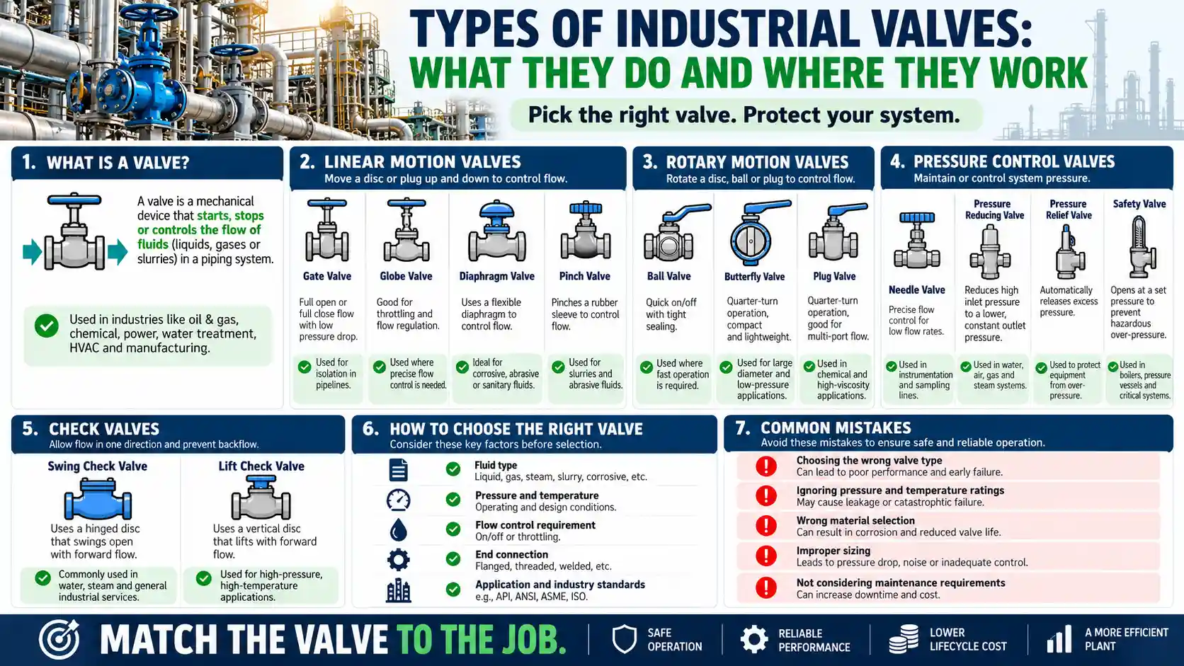
A globe valve is a linear-motion valve used to start, stop, or regulate the flow of fluid within a pipeline. It gets its name from the historically spherical shape of its outer body, which houses an internal baffle separating the two halves of the valve. Although modern designs have moved away from the true “globe” shape, the name has stuck.
Unlike a ball valve — which uses a rotating spherical ball — a valve globe design relies on a disc (or plug) that moves perpendicular to the seat to control flow. This makes globe valves distinct from gate or ball valves in both construction and function. According to Wikipedia’s overview of globe valves, the design incorporates a movable plug that screws into a stationary seat to fully shut off flow when needed.
Because of this mechanism, a globe control valve is widely regarded as one of the best options where frequent throttling and precise flow adjustment are required, rather than simple on/off operation.
3. Globe Valve Construction
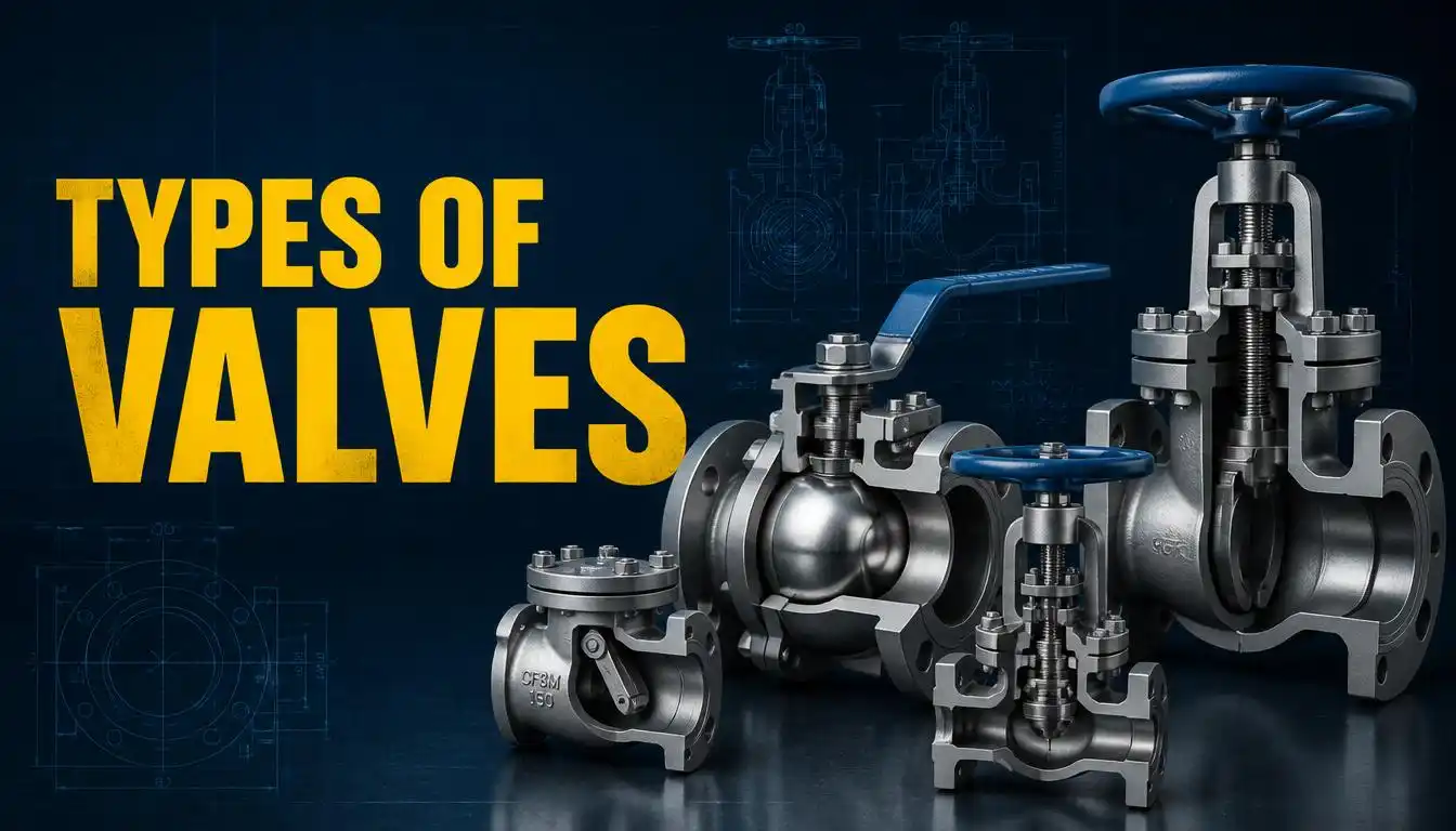
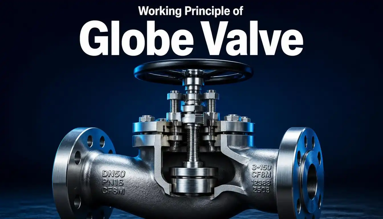
The construction of a globe valve is engineered for durability, ease of maintenance, and reliable sealing. The body forms the main pressure-containing structure, and its internal partition creates two separate flow chambers — one on the inlet side and one on the outlet side.
The disc moves vertically in relation to a stationary ring seat, and this axial (rather than rotational) motion is what gives globe valves their strong shut-off characteristics. The ScienceDirect engineering topic page on globe valves notes that these valves are typically built in sizes up to DN 600 and are widely used specifically for flow control applications rather than pure isolation duty.
The bonnet sits atop the body and provides a leak-tight enclosure through which the stem passes. Depending on the application, bonnets may be screw-in, bolted, or union-type — each offering different trade-offs between cost, pressure rating, and ease of disassembly.
4. Globe Valve Components
Understanding globe valve parts is essential to understanding how the valve performs its job. Here are the main globe valve components:
- Body – The primary pressure-retaining shell that houses all internal components and connects to the pipeline via flanged, threaded, or welded ends.
- Bonnet – Provides a leak-proof seal over the body while allowing the stem to pass through; often threaded or bolted for maintenance access.
- Stem – Transmits motion from the handwheel or actuator to the disc; may be threaded (rising stem, manual valves) or smooth (actuator-driven).
- Disc (Plug) – The closure element that seats against the valve seat to stop flow, or lifts away to allow it. Discs can be flat, plug-type, ball-type, or needle-type depending on the throttling requirement.
- Seat – A fixed ring against which the disc presses to create a seal; often replaceable to extend the valve’s service life.
- Handwheel/Actuator – The operating mechanism, either manual or automated (pneumatic, electric, or hydraulic), used to raise or lower the stem.
- Packing/Stuffing Box – Prevents leakage around the stem where it exits the bonnet.
Each of these parts of globe valve assemblies must be carefully matched to the specific pressure, temperature, and media conditions of the system for reliable long-term performance.
5. Globe Valve Working Principle
The core of the globe valve working principle lies in the linear relationship between the disc and the seat. When the handwheel or actuator rotates, it drives the stem in a straight line — either raising or lowering the disc relative to the seat.
Here’s how it works step by step:
- Opening the valve – Turning the handwheel (typically counterclockwise) lifts the stem and disc away from the seat, creating an annular opening through which fluid can pass.
- Regulating flow – The degree of disc lift directly controls the flow rate. A small lift permits a small opening for fine throttling, while a larger lift allows greater flow — this is what makes globe valves so effective for modulation.
- Closing the valve – Reversing the handwheel direction lowers the disc back onto the seat. As the gap narrows, flow is progressively restricted until the disc makes full contact with the seat, completely stopping flow.
- Sealing – Axial pressure applied through the stem forces the disc tightly against the seat, creating a positive, leak-resistant seal — a key reason globe valves are trusted for both throttling and shut-off duty.
Because the fluid must change direction as it passes through the valve body (often in a Z or S-shaped path), globe valves offer excellent control but at the cost of higher pressure drop compared to straight-through valve designs like gate or ball valves. Tameson’s guide on understanding globe valves explains this trade-off in more detail, noting that angle and Y-pattern designs help reduce this turbulence-related pressure loss.
6. Types of Globe Valves
There are several recognized types of globe valve designs, each suited to different piping layouts and flow requirements:
- T-Pattern (Z-Body) Globe Valve – The most common design, offering excellent throttling control but the highest resistance to flow due to the double change in flow direction.
- Angle Globe Valve – Positioned at a 90-degree bend in the pipeline, reducing one flow direction change and thereby lowering pressure drop compared to the T-pattern.
- Y-Pattern Globe Valve – Features an inclined seat and stem, allowing a straighter flow path that significantly reduces pressure loss while retaining strong throttling performance — ideal for high-velocity or high-pressure-drop services.
- Needle Globe Valve – Uses a slender, tapered disc for extremely fine flow control, commonly used in instrumentation and metering applications.
Selecting among these globe valve types depends largely on the acceptable pressure drop, available installation space, and the precision of control the application demands.
7. Globe Valve Applications
Thanks to their strong throttling capability and dependable sealing, globe valve application scenarios span nearly every process industry:
- Power Generation – Regulating steam and feedwater flow in boilers and turbines, where high temperature and pressure tolerance is critical.
- Oil & Gas – Managing the flow of crude oil, natural gas, and refined products across upstream and midstream operations.
- Chemical & Petrochemical Processing – Handling corrosive or hazardous chemical flows where precise dosing and shut-off matter.
- Water & Wastewater Treatment – Controlling flow rates during filtration, dosing, and distribution processes.
- HVAC Systems – Regulating hot and chilled water circuits in commercial building systems.
- Plumbing – Common household stop valves and outdoor hose bib taps use a simplified globe valve mechanism.
Cowan Dynamics’ detailed globe valve guide highlights how globe valves remain the preferred choice in power plants specifically because they combine high-temperature durability with fine control — an essential combination for turbine and boiler operations.
8. Advantages & Disadvantages
Advantages:
- Excellent throttling and flow modulation capability
- Reliable, tight shut-off when fully closed
- Shorter disc travel reduces wear on sealing surfaces, extending service life
- Seats and discs can be resurfaced or replaced, simplifying maintenance
- Suitable for high-pressure and high-temperature applications
Disadvantages:
- Higher pressure drop due to the internal change in flow direction
- Requires greater operating torque, especially in larger sizes
- Slower to open/close compared to quarter-turn valves like ball or butterfly valves
- More susceptible to cavitation and flashing under high differential pressure
- Generally more expensive to manufacture than simpler valve designs
9. Globe Valve vs Gate Valve
One of the most common comparisons engineers make is globe valve vs gate valve, since both are linear-motion valves but serve very different purposes:
| Feature | Globe Valve | Gate Valve |
|---|---|---|
| Primary Function | Flow regulation & throttling | On/off isolation |
| Flow Path | Changes direction (higher pressure drop) | Straight-through (lower pressure drop) |
| Operating Speed | Slower, multi-turn | Slower, multi-turn |
| Sealing Surface Wear | Lower (no sliding contact) | Higher (sliding disc/wedge) |
| Maintenance | Easier seat/disc replacement | More complex |
| Best Use Case | Frequent throttling | Full open/full close only |
In short, if your system needs precise, repeatable flow control, a globe valve is the superior choice. If you simply need to fully open or fully close a line with minimal pressure loss, a gate valve is usually more efficient.
10. Maintenance Tips
Proper maintenance significantly extends the service life of any globe type valve. Keep these practices in mind:
- Inspect packing regularly – Stem leakage is one of the most common failure points; tighten or replace packing as soon as leaks appear.
- Avoid forcing the handwheel – Never use extension wrenches to force a stuck valve open or closed, as this can damage internal threads or the stem.
- Flush new pipelines gradually – When commissioning a new line, open the valve slightly to let high-velocity flow clear out debris before full operation.
- Check seating surfaces periodically – Look for pitting, erosion, or wear on the disc and seat, especially in high-cycle or high-temperature service.
- Operate valves periodically – Valves left in one position for long periods are more prone to sticking or seizing; periodic cycling helps prevent this.
- Monitor for cavitation noise – Unusual vibration or noise during throttling may indicate cavitation, which can quickly erode internal components if left unaddressed.
11. FAQs
Q1: What is the main working principle of a globe valve?
A globe valve works by moving a disc linearly toward or away from a fixed seat, using a stem driven by a handwheel or actuator, to regulate or stop fluid flow.
Q2: Why is it called a “globe” valve?
The name comes from the historically spherical (globe-shaped) body design, even though many modern globe valves no longer have a true spherical shape.
Q3: Where are globe valves commonly used?
They’re widely used in power plants, oil and gas pipelines, chemical processing, water treatment, and HVAC systems where precise flow control is required.
Q4: What’s the difference between a globe valve and a ball valve?
A globe valve uses a linear disc-and-seat mechanism ideal for throttling, while a ball valve uses a rotating ball for quick, quarter-turn on/off operation with minimal pressure drop.
Q5: Can globe valves handle high pressure and temperature?
Yes, globe valves are well-suited to high-pressure and high-temperature service, which is why they’re commonly found in steam and boiler applications.
12. Conclusion
The globe valve working principle — a disc moving linearly against a fixed seat — may sound simple, but it’s precisely this mechanism that makes globe valves indispensable across countless industrial processes. From power plants to chemical processing lines, understanding globe valve construction, components, types, and proper maintenance helps engineers and procurement teams select the right valve for the job, ensuring safe, efficient, and long-lasting flow control.
Whether you’re specifying a globe control valve for a new project or troubleshooting an existing installation, keeping these fundamentals in mind will help you make informed, cost-effective decisions.