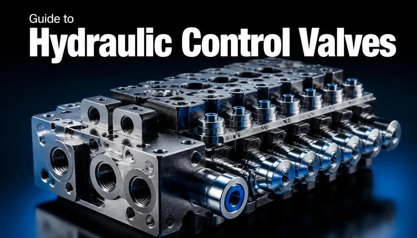
If you’ve ever operated an excavator, watched a hydraulic press stamp sheet metal, or wondered how a tractor’s loader arm lifts tons of material with a flick of a lever, you’ve witnessed a hydraulic control valve at work. These components are the unsung heroes of fluid power systems — silently directing, regulating, and controlling the flow of pressurized fluid that powers some of the heaviest machinery on the planet.
Whether you’re an engineer designing a new hydraulic circuit, a maintenance technician troubleshooting a stalled cylinder, or simply someone trying to understand how a hydraulic valve controller fits into a larger system, this guide breaks down everything you need to know — from basic hydraulic system components to the different types of directional control valves and how they stack up against pneumatic alternatives.
By the end of this article, you’ll understand not just what a hydraulic control valve is, but how to select the right one, how to maintain it, and where it fits into industrial applications ranging from construction equipment to manufacturing automation.
2. What is a Hydraulic Control Valve?
A hydraulic control valve is a mechanical or electromechanical device that regulates the flow, direction, and pressure of hydraulic fluid within a closed hydraulic system. Think of it as the “traffic controller” of a hydraulic circuit — it decides where fluid goes, how fast it gets there, and how much force it carries when it arrives.
At its core, control valve hydraulic systems perform three essential functions:
- Directing fluid flow — determining which path the fluid takes to reach an actuator (cylinder or motor)
- Regulating flow rate — controlling the speed at which an actuator moves
- Managing pressure — protecting the system from damage caused by excessive pressure buildup
Without a properly functioning hydraulic valve, a hydraulic system would be nothing more than a pump pushing fluid aimlessly through pipes. The valve is what transforms raw hydraulic power into controlled, useful mechanical motion — whether that’s lifting a bucket loader, clamping a workpiece, or steering heavy machinery.
3. Hydraulic System Basics
Before diving deeper into valve types, it helps to understand where a hydraulic valve control unit fits within the broader system. A typical hydraulic system consists of:
- Reservoir (tank) — stores the hydraulic fluid
- Pump — draws fluid from the reservoir and pressurizes it
- Valves — direct, regulate, and control the pressurized fluid
- Actuators — cylinders or motors that convert hydraulic energy into mechanical motion
- Piping and hoses — transport fluid between components
- Filters — keep the fluid clean and free of contaminants
Hydraulic systems rely on Pascal’s Law — the principle that pressure applied to a confined fluid is transmitted equally in all directions. This is what allows a small input force (like pressing a foot pedal) to generate an enormous output force (like lifting several tons). The valve sits at the heart of this transformation, controlling exactly how and when that force is applied.
According to detailed hydraulics coursework from the Philadelphia University engineering department, hydraulic valves generally fall into three functional categories: directional control valves, pressure control valves, and flow control valves — each serving a distinct role in keeping the system safe, efficient, and responsive.
4. Components of a Hydraulic Control Valve
A typical hydraulic control valve is made up of several key internal parts:
- Valve body — the housing that contains all internal components and ports
- Spool or poppet — the internal moving element that shifts to open or close flow paths
- Ports — external openings (commonly labeled P for pump, T for tank, and A/B for working ports) where fluid enters and exits
- Actuator mechanism — the method used to move the spool, which can be manual, mechanical, electrical (solenoid), pneumatic, or hydraulic (pilot-operated)
- Springs — used to return the valve to a default or neutral position when the actuating force is removed
- Seals — prevent internal and external leakage, maintaining system efficiency
The number of ports and the number of positions a valve can achieve are the two most important characteristics used to classify and select a valve, as outlined in this detailed breakdown of directional-control valve fundamentals from Power & Motion Tech.
5. Working Principle of a Hydraulic Control Valve
The working principle of a hydraulic control valve revolves around shifting an internal element — usually a spool or poppet — to open, close, or redirect flow paths within the valve body.
Here’s a simplified breakdown of how it works:
- Fluid enters the valve through the pump (P) port under pressure.
- An actuating signal (manual lever, electrical solenoid, or pilot pressure) causes the internal spool or poppet to shift position.
- The shifted spool aligns specific internal grooves with specific ports, creating a new flow path.
- Fluid is routed to the working port (A or B), which connects to the actuator — extending or retracting a cylinder, or rotating a motor.
- Return fluid flows back through the opposite working port and out through the tank (T) port, completing the circuit.
When the actuating signal is removed, springs typically return the spool to its neutral (centered) position, stopping fluid flow to the actuator or allowing it to recirculate back to the tank, depending on the valve’s center configuration (open, closed, tandem, or float center).
This shifting action can happen almost instantaneously — a characteristic sometimes referred to as “bang-bang” operation in on/off valves — or it can be modulated gradually in proportional valves, which allow for smoother acceleration and deceleration of the connected actuator, as explained in this comprehensive fluid power reference guide.
6. Types of Hydraulic Control Valves
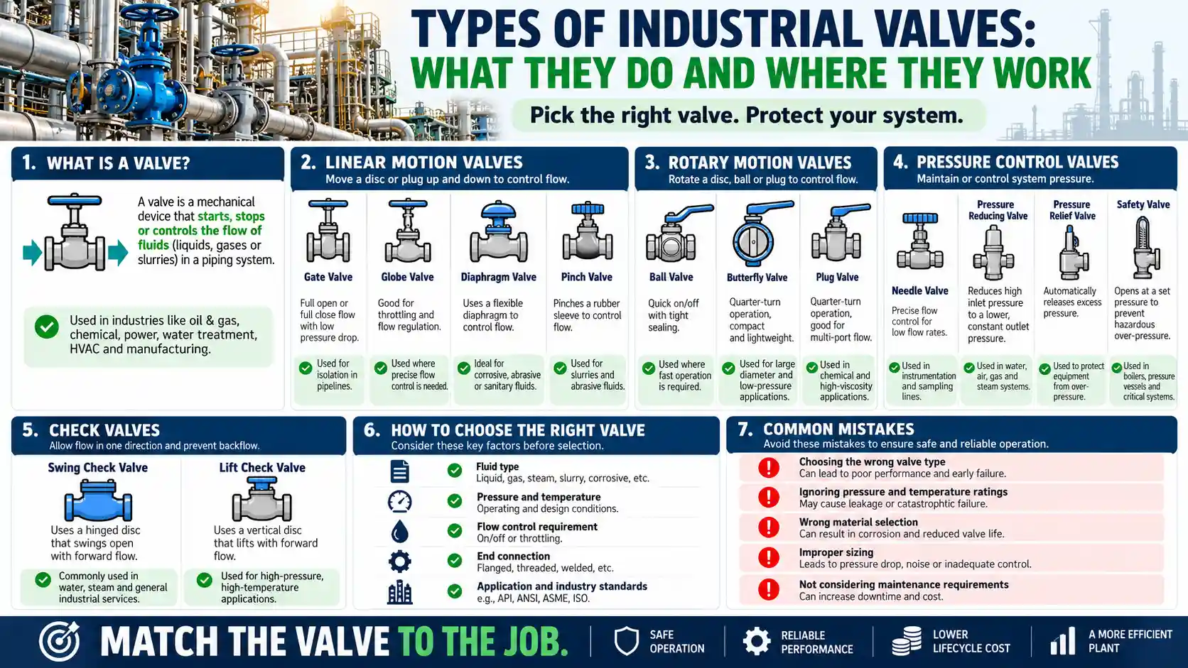
Not all hydraulic control valves perform the same job. Broadly, they’re grouped into three categories:
Directional Control Valves
These valves determine the path fluid takes through a circuit, controlling which way an actuator moves — extend, retract, rotate clockwise, or rotate counterclockwise.
Pressure Control Valves
These protect the system from damage by regulating pressure levels. Common subtypes include:
- Pressure relief valves — the most critical safety component in a hydraulic circuit, these open when system pressure exceeds a preset limit, preventing damage to pumps, hoses, and actuators
- Pressure reducing valves — lower pressure in a specific branch of the circuit
- Sequence valves — ensure one actuator completes its motion before another begins
- Counterbalance valves — maintain controlled resistance to prevent a load from free-falling under gravity
You May Also Like: What is a Control Valve ? Working, Types & Parts
Flow Control Valves
These regulate the rate of fluid flow, which directly determines actuator speed. They can be:
- Non-compensated — simple and cost-effective, but flow rate varies with pressure changes
- Pressure-compensated — automatically adjust to maintain a constant flow rate regardless of pressure fluctuations, offering more precise speed control
A detailed classification of these valve categories, including how pressure-compensated flow controls maintain accuracy under varying loads, is available in this guide to hydraulic valve types from Mobile Hydraulic Tips.
7. Directional Control Valves in Depth
Since directional control valve technology is arguably the most complex and widely discussed category, it deserves its own closer look.
How Directional Control Valves Are Classified
Directional control valves are typically categorized by:
- Number of ports (ways) — 2-way, 3-way, 4-way, or 5-way
- Number of positions — 2-position, 3-position, or occasionally 4-position
- Actuation method — manual, mechanical, solenoid, pneumatic, or hydraulic pilot
- Internal design — spool-type, poppet-type, or ball-type
Common Types of Directional Control Valves
- Check Valves — the simplest type, allowing flow in only one direction while blocking reverse flow
- Shuttle Valves — allow flow from either of two inlet sources to a common outlet, often used for backup or redundant pump systems
- 2-Way Valves — simple on/off control for a single flow path
- 3-Way Valves — used to control single-acting cylinders, featuring one pump port, one tank port, and one working port
- 4-Way Valves — the most common type for double-acting cylinders, featuring pressure, tank, and two working ports, allowing full bi-directional control
According to a detailed breakdown from Bailey International’s guide to directional control valves, 4-way valves are typically favored in double-acting cylinder applications because they provide far greater versatility and control over hydraulic flow compared to 3-way designs.
Spool Center Configurations
When a 3-position directional valve returns to neutral, its “center condition” determines system behavior:
- Open Center — allows continuous flow from pump to tank, commonly paired with fixed-displacement pumps
- Closed Center — blocks all ports, typically used with pressure-compensated, variable-displacement pumps for better energy efficiency
- Tandem Center — blocks working ports while allowing free pump-to-tank flow, common in mobile equipment
- Float Center — allows the actuator to move freely under external force, useful for applications like snowplow blades
Choosing the correct center configuration significantly affects system efficiency, energy consumption, and component longevity — making it one of the most important decisions in hydraulic valve control design.
8. Pneumatic vs Hydraulic Control Valves
A common point of confusion for engineers and buyers alike is the difference between pneumatic control valve systems and hydraulic ones. While both serve similar functions — directing and regulating fluid flow — the medium they control and their ideal applications differ significantly.
| Feature | Hydraulic Control Valve | Pneumatic Control Valve |
|---|---|---|
| Medium | Oil (incompressible) | Compressed air (compressible) |
| Force output | High force, heavy-duty | Lower force, lightweight tasks |
| Precision | Very high | Moderate |
| Speed | Slower, controlled | Faster response |
| Cleanliness | Can leak oil | Clean (air-based) |
| Typical use | Construction, industrial presses | Packaging, assembly lines |
Because oil is virtually incompressible, hydraulic systems can generate significantly higher force and offer more precise control — which is why heavy machinery like excavators and industrial presses rely on hydraulics. Pneumatic systems, on the other hand, use compressed air, which is compressible, making them faster and cleaner but less suited for high-force applications.
A solenoid pneumatic valve operates similarly to a hydraulic solenoid valve in principle — both use an electromagnetic coil to move a plunger and open or close flow paths — but pneumatic solenoid valves are generally simpler, smaller, and better suited for quick on/off cycling of air rather than heavy fluid loads. As explained in this comparison of pneumatic and hydraulic solenoid valve differences, hydraulic solenoid valves are built for high thrust and precision even in extreme environments, while pneumatic versions prioritize speed and simplicity.
When deciding between a pneumatic air valve and a hydraulic valve for your application, consider:
- Force requirements — hydraulics for heavy loads, pneumatics for lighter tasks
- Cleanliness needs — pneumatics for food/pharma environments where oil contamination is a concern
- Response speed — pneumatics for rapid cycling, hydraulics for controlled, powerful motion
- Energy costs — compressed air systems can consume significant electricity, so efficiency should be factored into long-term operating costs
9. Industrial Applications of Hydraulic Control Valves
Hydraulic control valves are found across nearly every heavy industry. Some of the most common applications include:
- Construction & Heavy Machinery — Excavators, loaders, and bulldozers rely on directional control valves for precise control over digging, lifting, and maneuvering functions.
- Agriculture — Tractors use hydraulic valves to control three-point hitches, loaders, and various implements for plowing and harvesting.
- Manufacturing & Industrial Presses — Hydraulic presses use pressure and flow control valves for precise force application during stamping and forming operations.
- Aerospace — Servo-controlled hydraulic valves manage flight control surfaces and landing gear systems with extreme precision.
- Material Handling — Forklifts and cranes use directional valves to control lifting, lowering, and tilting functions.
- Mobile Equipment — Snowplows, dump trucks, and utility vehicles use specialized valve configurations (like float centers) for specific operational needs.
As highlighted in this overview of directional control valve applications from TRADESAFE, the versatility of these valves — from ancient watermill mechanisms to today’s precision-engineered systems — has made them indispensable across virtually every sector that relies on mechanized force.
10. Maintenance & Troubleshooting
Like any mechanical component under constant pressure and movement, hydraulic control valves require regular maintenance to avoid costly downtime. Here are the most common issues and how to address them:
Common Problems
- Contamination — Dirt, debris, or water in the hydraulic fluid is the number one cause of valve failure. Contaminated fluid can cause spools to stick, seals to wear prematurely, and internal components to score.
- Fluid Leakage — Worn seals or damaged O-rings can cause internal or external leaks, reducing system efficiency and pressure.
- Sticking Spools — Often caused by contamination, corrosion, or misalignment, sticking spools prevent the valve from shifting properly.
- Overheating — Excessive system pressure or restricted flow can cause fluid temperatures to rise, degrading both the fluid and valve components over time.
- Cylinder Creep — A worn spool valve with metal-to-metal fit may allow a cylinder to slowly drift under load, even when the valve is centered.
Preventive Maintenance Tips
- Keep fluid clean — Use high-quality filters and change hydraulic fluid according to manufacturer recommendations.
- Monitor for water contamination — Water in hydraulic fluid accelerates corrosion and valve wear.
- Inspect seals regularly — Replace worn seals before they cause significant leakage.
- Check for unusual noises — A “hammering” sound during valve shifting can indicate fluid hammer, a symptom of rapid pressure changes that stresses system components.
- Test relief valve settings periodically — Ensure pressure relief valves are functioning correctly to protect the system from damage.
Hydraulic parts specialists note that the best way to prevent directional control valve failure is proactive contamination control — keeping oil clean, cool, and dry significantly extends valve life, as detailed in this practical guide on how directional control valves work and fail.
11. FAQs
Q1: What is the difference between a directional control valve and a pressure control valve?
A directional control valve determines which way fluid flows (controlling actuator direction), while a pressure control valve regulates how much pressure is in the system, protecting components from damage.
Q2: How do I know if I need a 3-way or 4-way directional valve?
Use a 3-way valve for single-acting cylinders (which only need pressure in one direction) and a 4-way valve for double-acting cylinders that require bi-directional control.
Q3: Can pneumatic and hydraulic control valves be used interchangeably?
No. While the operating principles are similar, pneumatic valves are designed for compressible air and lower-force applications, while hydraulic valves are built for incompressible oil and high-force, high-precision tasks.
Q4: What causes a hydraulic control valve to fail prematurely?
The most common cause is fluid contamination — dirt, debris, or water in the hydraulic fluid — which damages seals, scores internal surfaces, and causes spools to stick.
Q5: What does “open center” and “closed center” mean in a directional valve?
These terms describe the valve’s neutral position behavior. Open center allows continuous fluid flow from pump to tank when idle, while closed center blocks all flow, typically used with variable-displacement, pressure-compensated pumps.
Q6: How often should hydraulic control valves be inspected?
This depends on usage intensity, but most industrial systems benefit from monthly visual inspections and fluid analysis every 3–6 months to catch contamination or wear early.
12. Conclusion
The hydraulic control valve may be a small component relative to the machinery it powers, but its role is nothing short of essential. From directing fluid flow through complex directional control valve configurations to regulating pressure and flow with precision engineering, these valves are what transform raw hydraulic power into controlled, useful work.
Whether you’re specifying a hydraulic valve controller for a new industrial system, comparing pneumatic control valve options for a lighter-duty application, or troubleshooting a hydraulic valve control issue on existing machinery, understanding the fundamentals covered in this guide will help you make informed decisions — and keep your systems running efficiently for years to come.
If you’re evaluating valve options for a specific application, consider consulting with a fluid power specialist who can help match valve type, configuration, and actuation method to your exact operational requirements.