1. Introduction
If you’ve ever looked at a Piping and Instrumentation Diagram (P&ID) and felt like you were staring at a page of hieroglyphics, you’re not alone. Every industrial drawing is built on a language of shapes, lines, and small notations — and valves are one of the busiest parts of that language. A single missed detail in a valve symbol can mean the difference between correctly specifying a shutoff valve and accidentally installing a throttling valve in the wrong place.
Understanding valve symbols is a foundational skill for piping engineers, instrumentation technicians, project estimators, and even procurement teams. Whether you’re reading a control valve symbol, trying to identify the symbol of gate valve, or decoding a flow control valve symbol buried in a dense P&ID, this guide breaks it all down in plain language.
By the end of this article, you’ll be able to confidently read valve drawing symbols, understand what each shape and line represents, avoid common misreadings, and know exactly where to look up any symbol you’re unsure about.
2. What are Valve Symbols?
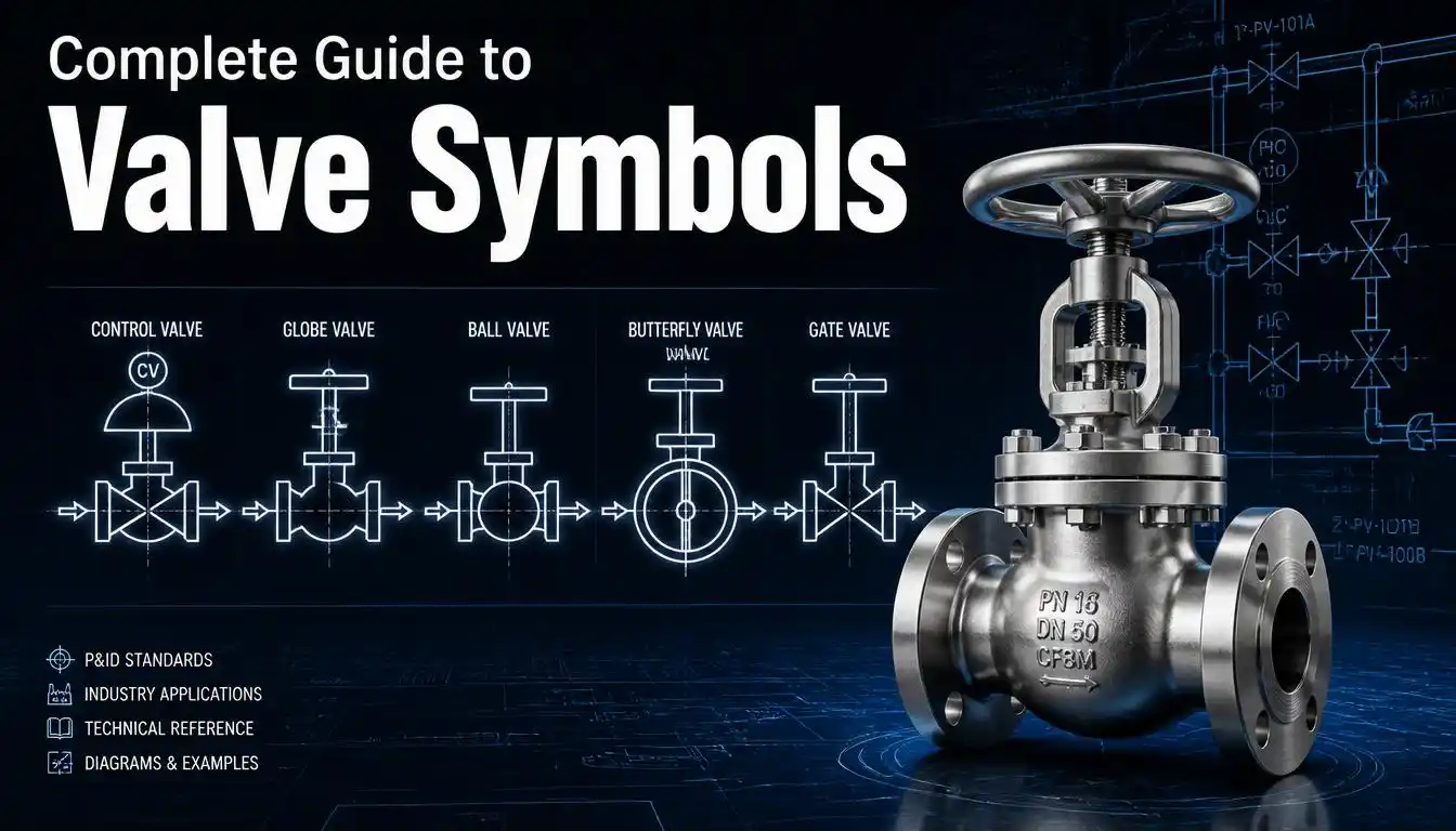
Valve symbols are standardized graphical representations used in engineering drawings — primarily P&IDs and isometric drawings — to depict the type, function, and operating method of a valve within a piping system. Instead of writing out “gate valve, manually operated, normally open” every time a valve appears on a drawing, engineers use a compact symbol that conveys all of this information at a glance.
Most valve symbols share a common foundation: two triangles pointing toward each other, often called a “bow-tie” shape. This base shape represents a generic two-way valve. What differentiates one valve type from another is the small addition inside or around that bow-tie — a filled circle, an open circle, a diagonal line, a vertical bar, or an arrow.
On top of the basic body shape, valve symbols often include:
- Actuator marks — showing whether the valve is manual, pneumatic, electric, hydraulic, or solenoid-operated
- Fail-safe indicators — such as FO (fail open), FC (fail closed), or FL (fail last)
- Tag numbers — connecting the symbol to a valve list, datasheet, or instrument index
- Line and connection details — indicating flanged, threaded, socket-welded, or butt-welded ends
Together, these elements let a trained reader look at a single symbol and immediately understand what the valve does, how it’s operated, and how it behaves in an emergency.
3. Importance of P&ID Symbols
P&ID symbols exist to create a universal, unambiguous language across an entire project team — designers, fabricators, operators, and maintenance staff alike. A P&ID typically serves as the master reference throughout a project’s lifecycle: guiding construction and commissioning, informing control system programming, supporting HAZOP (Hazard and Operability) studies, and acting as a go-to troubleshooting reference once a plant is operational.
Because these diagrams are used by so many different teams — often across different companies, countries, and even decades — consistency in symbol usage isn’t optional. A ball valve symbol drawn in Texas needs to mean the same thing as a ball valve symbol drawn in Singapore. This is why most organizations follow standardized symbol libraries, such as those published by ISA (International Society of Automation) or ISO, while also maintaining a project-specific legend to clarify any custom notations.
Getting valve symbols wrong on a drawing isn’t a minor cosmetic issue. It can lead to the wrong equipment being ordered, incorrect installation, safety risks during operation, or costly rework. This is exactly why understanding p&id valve symbols thoroughly is considered essential training for anyone working in process industries — oil and gas, chemical processing, power generation, water treatment, and manufacturing alike.
If you want a deeper technical breakdown of full P&ID symbol families beyond just valves, this comprehensive P&ID symbols reference is a solid place to start.
4. Control Valve Symbol
The control valve symbol represents one of the most functionally important valves on any P&ID, because it’s the valve responsible for automated, real-time flow regulation based on signals from a control system.
A control valve symbol is typically drawn as a valve body (often a globe-style bow-tie) with an actuator symbol mounted on top, connected by a stem line. The actuator might be shown as a diaphragm dome, a piston, a motor (marked with an “M”), or a solenoid. Below or beside the symbol, you’ll usually see a tag such as FCV (Flow Control Valve), PCV (Pressure Control Valve), or TCV (Temperature Control Valve) — the letters indicating exactly what process variable the valve is regulating.
Key details typically shown alongside a control valve symbol include:
- Actuator type (pneumatic, electric, hydraulic)
- Fail-safe position — FO (fail open), FC (fail closed), or FL (fail locked/last), indicating where the valve moves to if it loses power or air supply
- Signal line — a dashed line connecting the valve to its controller, showing it’s part of an automated control loop
According to industry references on oil and gas P&ID reading, engineers often add specific notes below the control valve symbol covering size, pressure rating, and connection type — for example, indicating a 2-inch ANSI 300 raised-face valve. You can see real-world examples of this in Kimray’s breakdown of common control valve symbols.
5. Flow Control Valve Symbol
The flow control valve symbol is a specific type of control valve symbol used when a valve’s primary job is to regulate the rate of fluid flow through a line, rather than pressure, temperature, or level.
Visually, a flow control valve symbol looks much like a standard control valve — a valve body topped by an actuator — but it’s specifically tagged FCV and typically connects to a flow transmitter (FT) or flow indicator controller (FIC) elsewhere on the diagram via a signal line. This tagging is critical: without it, you’d only know a valve is automated, not what it’s automating.
Flow control valves are especially common in:
- Chemical dosing and blending systems, where precise flow ratios matter
- Cooling water systems, where flow needs to match heat load
- Any process loop where a downstream flow rate must be held at a setpoint
When you’re scanning a drawing for flow control valve symbols, look for the combination of three things together: the actuated valve body, the FCV tag, and a signal line running back to a flow transmitter. Missing any one of these means you might be looking at a different type of automated valve, such as a pressure or level control valve that simply looks similar at first glance.
6. Gate Valve Symbol
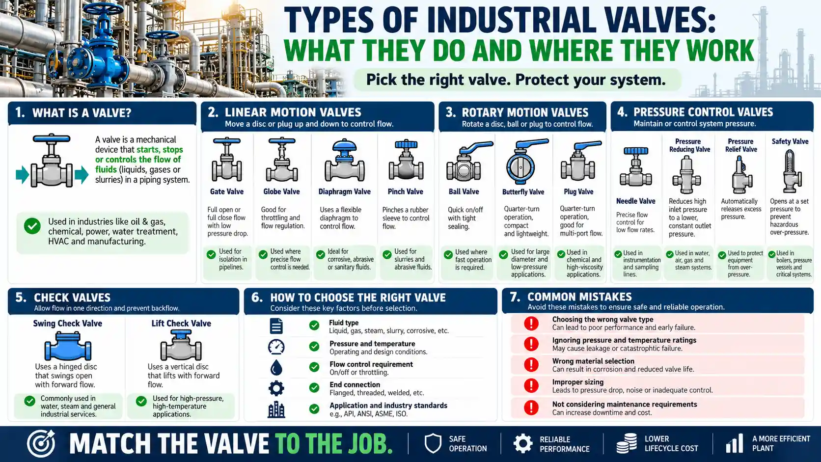
The gate valve symbol is one of the most frequently seen symbols on any P&ID, since gate valves are the workhorse of on/off isolation throughout piping systems.
The symbol of gate valve builds on the basic bow-tie body by adding a vertical line (or sometimes a solid bar) through the center point where the two triangles meet. Some drafting standards instead show a rectangular box with a horizontal line inside, though the vertical-bar-through-bow-tie version is the most widely used convention. This addition visually represents the sliding “gate” mechanism that lifts up and out of the flow path when the valve is open.
A few important things to know about reading gate valve symbols:
- Gate valves are designed for full open or full closed operation only — they are not meant for throttling or partial flow regulation, and using them that way can damage the internal gate over time
- Variants like wedge gate, slab gate, and knife gate valves all share this same base symbol, with service-specific notation added in the tag or legend when needed
- A blacked-out (filled) version of the symbol is sometimes used to indicate a normally closed state, while the letters “NC” or “NO” are also commonly used for clarity
Because gate valves appear so frequently, mixing them up with globe valves is a common beginner mistake — more on that distinction below.
7. Ball Valve Symbol
The ball valve symbol is built on the same bow-tie foundation but adds an open (unfilled) circle at the center, representing the rotating ball inside the valve body that controls flow through a bored passage.
Ball valves are quarter-turn devices, meaning a 90-degree rotation of the handle takes them from fully open to fully closed. This makes them ideal for quick shutoff applications where speed and a tight seal matter more than fine flow control. Some drafting standards represent the ball valve with a small circle and horizontal line combination instead of a fully open circle, so it’s always worth checking the specific project’s symbol legend before assuming.
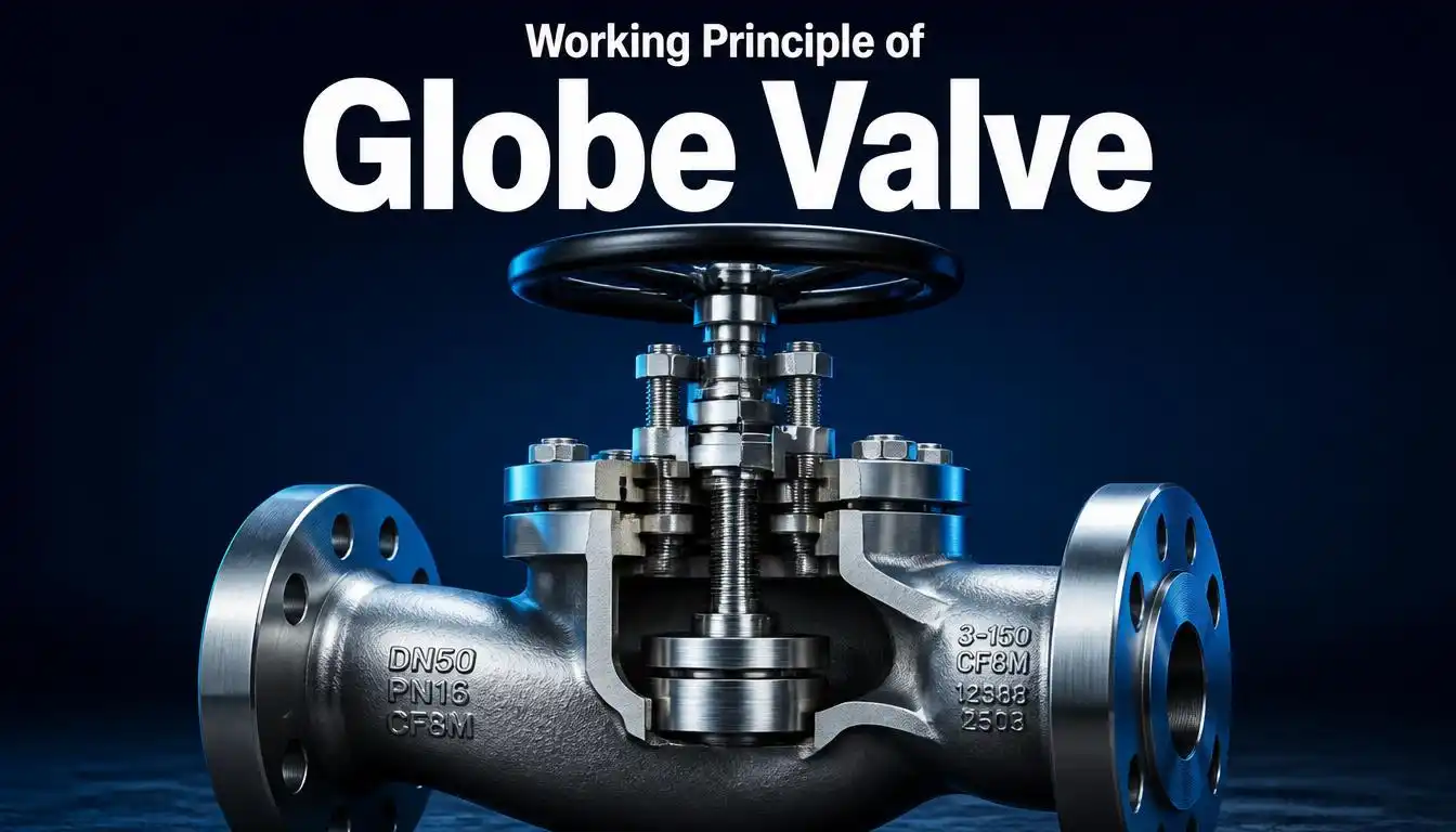
One detail worth remembering: a ball valve symbol and a globe valve symbol can look nearly identical at a glance. The distinguishing factor is usually whether that central circle is filled (globe valve) or open/unfilled (ball valve) — a subtle but critical difference. If you regularly work across drawings from different companies, Tameson’s guide to P&ID valve symbols offers helpful side-by-side visuals for exactly this kind of comparison.
Ball valves also come in floating-ball and trunnion-mounted variants, which may be indicated through tag notes or specific center markings rather than a completely different base symbol.
8. Butterfly Valve Symbol
The butterfly valve symbol is one of the more visually distinct entries in the valve symbol family. It’s typically shown as a circle (representing the pipe cross-section) bisected by a diagonal or straight line running through the center, which represents the rotating disc inside the valve.
Some drafting conventions instead show the classic bow-tie body with a diagonal disc line running across it, sometimes paired with a small filled circle to indicate the pivot point of the disc. Because there’s more than one accepted convention in circulation, checking the specific drawing’s legend is especially important for this symbol type.
Butterfly valves are popular in large-diameter piping because their design is compact, lightweight, and quick to operate compared to gate or globe valves of the same size. They’re commonly used for both isolation and, in high-performance variants, moderate throttling duties.
When reading a butterfly valve symbol, also watch for the end-connection notation nearby — flanged, wafer, or lug-style butterfly valves all use the same base symbol but have very different installation requirements, so the connection type usually needs to be specified separately in the tag or notes.
9. Reading Valve Symbols in Engineering Drawings
Reading valve symbols confidently on a real-world drawing comes down to a systematic approach. Here’s a practical method:
- Identify the body shape first. Is it a plain bow-tie, or does it have something inside (a circle, a line, a bar)? This tells you the base valve type — gate, globe, ball, or butterfly.
- Check for an actuator symbol. A symbol on a stem above the valve body means it’s automated. No actuator usually means it’s manually operated (sometimes shown with a small handwheel icon).
- Read the tag. Letters near the symbol — like FCV, PCV, TCV, XV, or MOV — tell you the valve’s specific function within the control scheme.
- Look for fail-safe notation. FO, FC, or FL tells you what the valve does if it loses power, air, or signal — critical for safety-related valves.
- Cross-reference the legend. Every P&ID includes a symbol legend or key. Since conventions vary slightly between companies and industries, always confirm your interpretation against the project-specific legend rather than relying purely on memory.
- Note the connection type. Flanged, threaded, socket-welded, or butt-welded connections affect installation and are usually indicated near the symbol or in an accompanying isometric drawing.
Following this sequence consistently turns what looks like a wall of confusing shapes into a readable, logical story about how fluid moves — and is controlled — through the system.
10. Common Mistakes
Even experienced engineers occasionally misread valve symbols, especially when switching between drawings from different companies or countries. Here are the most frequent errors to watch for:
- Confusing gate and globe valve symbols. Both use the bow-tie base; the globe valve’s filled center circle versus the gate valve’s plain vertical line is easy to miss at a quick glance.
- Mixing up ball and globe valves. As noted earlier, an open circle (ball) versus a filled circle (globe) is a small but crucial visual difference.
- Ignoring the actuator and tag entirely. A valve symbol without checking its actuator and tag tells you almost nothing about how the valve actually functions in the control scheme.
- Assuming symbols are universal without checking the legend. While standards like ISA-5.1 promote consistency, individual companies and even individual projects sometimes use slightly modified conventions.
- Overlooking fail-safe notation. Skipping FO/FC/FL details can lead to a dangerous misunderstanding of how a system behaves during a power or air failure — a serious issue during HAZOP reviews.
- Not distinguishing isometric symbols from P&ID symbols. The same valve type is often drawn differently between a P&ID and an isometric piping drawing, particularly regarding end connections. For a detailed side-by-side comparison, Hard Hat Engineer’s guide to P&ID and isometric valve symbols is a useful reference.
Avoiding these mistakes largely comes down to slowing down, checking the legend, and never assuming a symbol’s meaning purely from its rough shape.
11. Downloadable Symbol Chart
To make all of this easier to reference on the job, we recommend keeping a valve symbol chart handy — either printed at your desk or saved to your phone. A good chart should cover, at minimum:
- Gate, globe, ball, butterfly, plug, and check valve symbols
- Actuator symbols (manual, pneumatic, electric, hydraulic, solenoid)
- Common tag abbreviations (FCV, PCV, TCV, LCV, XV, MOV, PSV)
- Fail-safe position notations (FO, FC, FL)
Several industry sites offer free downloadable PDF references you can save for quick lookup. Union Valve’s P&ID symbol guide and Process Valves’ UK-based symbol breakdown both include clear visual charts worth bookmarking alongside this article. For a more manufacturer-oriented take with additional variants, DomBor’s valve symbols guide is another helpful bookmark.
(Tip: create your own one-page cheat sheet by screenshotting the symbol charts from two or three of these sources — cross-referencing multiple charts helps you catch any project-specific variations early.)
12. FAQs
Q1: What is the most common valve symbol used in P&IDs?
The two-triangle “bow-tie” shape is the base symbol for nearly all two-way valves. It becomes a gate, globe, ball, or butterfly valve symbol depending on the small addition — a line, filled circle, open circle, or diagonal — placed at its center.
Q2: How do I tell a control valve symbol apart from a manual valve symbol?
Look for an actuator symbol (like a diaphragm dome, piston, or motor icon) mounted on a stem above the valve body, along with a tag such as FCV or PCV. A plain valve body without an actuator or control tag is typically manually operated.
Q3: Are valve symbols the same across every company and country?
Mostly, yes — many organizations follow ISA or ISO-based conventions for consistency. However, minor variations do exist between companies and industries, which is why every P&ID includes its own symbol legend that should always be checked first.
Q4: What does FO, FC, and FL mean next to a valve symbol?
These indicate the valve’s fail-safe position: FO means fail open, FC means fail closed, and FL means fail last (or locked) — describing where the valve moves to if it loses air, power, or signal.
Q5: What’s the easiest way to learn valve symbols quickly?
Start with the four most common types — gate, globe, ball, and butterfly — since they share the same base shape with small distinguishing marks. Practice reading real P&IDs alongside a symbol chart until the shapes become second nature.
13. Conclusion
Valve symbols might look intimidating at first, but they’re built on a surprisingly logical and consistent system once you understand the underlying pattern. Nearly every symbol starts with the same bow-tie base, with small additions — a line, a circle, a diagonal mark — telling you exactly what type of valve you’re looking at. Layer on actuator symbols, tags, and fail-safe notation, and a single small icon on a drawing can tell you almost everything you need to know about how that valve behaves.
Whether you’re troubleshooting a plant issue, reviewing a new P&ID before construction, or simply trying to sharpen your engineering drawing literacy, mastering valve symbols — from the gate valve symbol to the control valve symbol and everything in between — is one of the most practical skills you can build in process and piping engineering. Keep a symbol chart nearby, always check the project legend, and with a bit of practice, reading even the busiest P&ID will start to feel second nature.