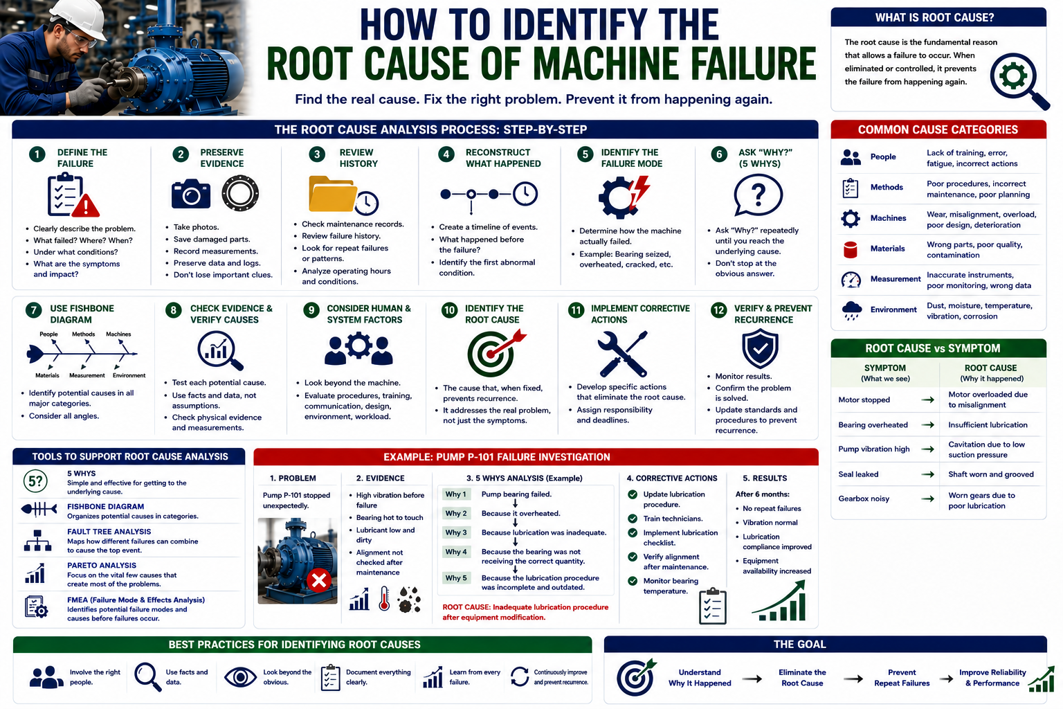
Machine failures are one of the biggest challenges faced by industrial facilities. A failed pump, motor, gearbox, compressor, conveyor, or production machine can result in unexpected downtime, expensive repairs, production losses, and safety risks.
When a machine fails, the immediate response is often to repair or replace the damaged component and return the equipment to service. While this restores operation, it does not always solve the actual problem.
If the underlying cause remains unidentified, the same machine may fail again.
This is why Root Cause Analysis (RCA) is an essential part of modern maintenance and reliability engineering. Rather than asking only what component failed, engineers investigate why the failure occurred and what can be done to prevent it from happening again.
This guide explains how maintenance teams can systematically identify the root cause of machine failure.
What Is the Root Cause of a Machine Failure?
The root cause is the fundamental reason that allowed a failure to occur and, when eliminated or controlled, can prevent the failure from recurring.
It is important to distinguish between the symptom, failure mode, immediate cause, and root cause.
For example:
Symptom: Motor stopped.
Failure mode: Motor overheated.
Immediate cause: Motor was drawing excessive current.
Underlying cause: Excessive mechanical loading.
Root cause: Pump and motor were incorrectly aligned after installation.
Replacing the motor may restore production, but the alignment problem can cause the replacement motor to fail as well.
A proper investigation therefore goes beyond the failed component.
Why Identifying the Root Cause Matters
Repeated equipment failures can become extremely expensive.
Consider a production pump that fails several times each year. Every breakdown may require:
- Emergency maintenance
- Spare parts
- Technician labor
- Equipment isolation
- Production downtime
- Troubleshooting
- Testing and commissioning
If the organization simply replaces the failed component each time, the same costs continue.
Root Cause Analysis changes the approach from:
Failure → Repair → Failure → Repair
to:
Failure → Investigation → Root Cause → Corrective Action → Verification → Prevention
The objective is to eliminate or control the conditions responsible for recurring failures.
Step 1: Clearly Define the Failure
The first step is to create an accurate problem statement.
Avoid vague descriptions such as:
“Pump failed.”
Instead, provide specific information:
“Pump P-101 stopped during normal operation after abnormal vibration increased and the motor protection system activated.”
A good problem statement should explain:
- What failed?
- Where did it fail?
- When did it fail?
- Under what operating conditions?
- What was the consequence?
- What symptoms were observed?
A precise problem statement keeps the investigation focused.
Step 2: Preserve Evidence
Evidence can disappear quickly after a machine failure.
Before dismantling equipment or replacing components, maintenance teams should document the condition of the machine.
Useful evidence includes:
- Photographs
- Damaged components
- Vibration readings
- Temperature readings
- Pressure readings
- Electrical measurements
- Lubricant condition
- Alarm records
- Operator observations
- Equipment settings
For example, a damaged bearing may contain important evidence about the failure mechanism. If it is discarded before inspection, valuable information may be lost.
Step 3: Review Equipment History
Historical maintenance data can reveal whether the failure is isolated or recurring.
Review:
- Previous work orders
- Failure reports
- Maintenance history
- Component replacements
- Inspection records
- Condition-monitoring data
- Operating hours
- Downtime history
Suppose a gearbox has failed three times in eighteen months.
That history immediately suggests that the organization should investigate why the gearbox repeatedly fails rather than treating the latest failure as an isolated event.
Historical data can also reveal patterns between failure frequency and operating conditions.
You may also like: Different Types of Pumps Used in Industry & Home Every Day
Step 4: Reconstruct What Happened
Create a timeline of events leading up to the failure.
For example:
08:00 — Machine operating normally
10:15 — Operator reports unusual noise
11:00 — Vibration begins increasing
11:30 — Temperature rises
11:45 — Machine trips
12:00 — Maintenance team begins inspection
This timeline helps identify what changed before the failure.
The first abnormal condition may provide an important clue about the actual failure mechanism.
Step 5: Identify the Failure Mode
The next step is to determine how the machine failed.
Common failure modes include:
- Bearing seizure
- Shaft fracture
- Gear tooth wear
- Seal leakage
- Motor overheating
- Electrical short circuit
- Excessive vibration
- Corrosion
- Cracking
- Lubricant degradation
- Impeller damage
Knowing the failure mode allows engineers to investigate potential causes systematically.
For example, if a bearing failed through overheating, possible causes include:
- Insufficient lubrication
- Excessive lubrication
- Misalignment
- Excessive loading
- Contamination
- Incorrect bearing installation
Step 6: Ask “Why?”
One of the simplest Root Cause Analysis techniques is the 5 Whys.
The method involves repeatedly asking why a failure occurred.
Example:
Problem: Bearing failed.
Why did the bearing fail?
It overheated.
Why did it overheat?
Lubrication was inadequate.
Why was lubrication inadequate?
The bearing was not receiving the specified quantity of lubricant.
Why was the quantity incorrect?
The lubrication procedure did not specify the required quantity.
Why did the procedure lack the specification?
The maintenance standard had not been updated after an equipment modification.
The investigation has now moved beyond the bearing itself and identified a maintenance-system problem.
The number of “whys” does not have to be exactly five. The important objective is to continue investigating until the team reaches a cause that can be effectively controlled.
Step 7: Use a Fishbone Diagram
A Fishbone Diagram, also called an Ishikawa or Cause-and-Effect Diagram, is another useful RCA tool.
Potential causes can be organized into categories such as:
People
- Insufficient training
- Human error
- Incorrect operating procedure
Equipment
- Poor design
- Component failure
- Equipment deterioration
Methods
- Incorrect maintenance procedure
- Inadequate inspection
- Incorrect installation process
Materials
- Wrong spare part
- Poor-quality component
- Contaminated lubricant
Measurement
- Incorrect sensor readings
- Poor calibration
- Inadequate monitoring
Environment
- Dust
- Moisture
- Excessive temperature
- Corrosive conditions
This approach helps maintenance teams avoid focusing too narrowly on one possible cause.
Step 8: Check for Physical Evidence
A suspected root cause should be supported by evidence.
For example, if misalignment is suspected, engineers can check:
- Shaft alignment measurements
- Coupling condition
- Vibration patterns
- Bearing wear
- Installation records
If poor lubrication is suspected, engineers can examine:
- Lubricant quantity
- Lubricant condition
- Lubrication records
- Contamination
- Lubricant specification
The question should always be:
“What evidence proves or disproves this potential cause?”
This prevents RCA investigations from becoming based purely on opinions.
Step 9: Consider Human and System Factors
Machine failures are not always caused by physical equipment problems.
Human and organizational factors can also contribute.
Examples include:
- Inadequate training
- Poor procedures
- Weak communication
- Incorrect work instructions
- Production pressure
- Poor planning
- Inadequate supervision
- Insufficient spare parts
- Poor equipment documentation
For example, a technician may install the wrong bearing because the equipment database contains incorrect part information.
In this situation, simply telling the technician to “be more careful” does not address the system-level cause.
A stronger corrective action would be to improve equipment records, part identification, procedures, and verification processes.
Step 10: Determine Whether the Cause Is Root or Immediate
Before finalizing the investigation, ask whether the identified cause can explain the failure and whether eliminating it would reasonably prevent recurrence.
For example:
Bearing failed because of overheating.
This describes an important condition, but it may not be the root cause.
Further investigation might reveal:
Overheating → Excessive friction → Poor lubrication → Incorrect lubrication quantity → Inadequate maintenance procedure
The deeper cause provides a more useful opportunity for prevention.
Step 11: Develop Corrective Actions
Once the root cause is confirmed, corrective actions should address it directly.
Potential actions include:
- Correcting equipment alignment
- Modifying equipment design
- Updating maintenance procedures
- Changing lubrication practices
- Improving operator training
- Installing condition monitoring
- Changing component specifications
- Improving environmental controls
- Revising inspection intervals
- Improving spare-parts management
Corrective actions should be specific and measurable.
Instead of:
“Improve maintenance.”
use:
“Update the pump alignment procedure and require alignment verification after every motor replacement.”
The second action is much easier to implement and verify.
Step 12: Verify That the Problem Has Been Eliminated
A Root Cause Analysis is not complete when the repair is finished.
The organization should verify whether the corrective action actually improved reliability.
Useful measures include:
- Repeat failure frequency
- MTBF
- MTTR
- Equipment availability
- Vibration trends
- Temperature trends
- Maintenance costs
- Unplanned downtime
For example, if a pump previously experienced four bearing failures per year and experiences none after corrective action, this provides evidence that the improvement was effective.
Common Mistakes When Identifying Root Causes
Several mistakes can weaken an investigation.
Stopping at the Failed Component
Finding a broken bearing is not the same as finding why it broke.
Blaming the Operator
Human error may be involved, but the investigation should also examine procedures, training, equipment design, and organizational factors.
Ignoring Historical Data
Previous failures often contain valuable clues.
Relying on Assumptions
A technically plausible explanation should still be supported by evidence.
Implementing Weak Corrective Actions
Replacing a component may restore operation without preventing recurrence.
Failing to Follow Up
Corrective actions should be verified after implementation.
Tools That Can Help Identify Root Causes
Maintenance teams can use several analytical techniques depending on the complexity of the failure.
5 Whys
Useful for straightforward recurring problems.
Fishbone Diagram
Useful for organizing multiple potential causes.
Fault Tree Analysis
Useful for complex systems with multiple failure pathways.
FMEA
Useful for identifying potential failure modes, causes, and effects before failures occur.
Pareto Analysis
Useful for identifying the small number of failure causes responsible for a large percentage of problems.
Combining these tools with maintenance history and condition-monitoring information can significantly improve failure investigations.
How Technology Can Improve Root Cause Analysis
Modern maintenance systems can provide more information for failure investigations.
A CMMS can provide:
- Equipment history
- Work orders
- Failure codes
- Repair information
- Maintenance costs
Condition-monitoring systems can provide:
- Vibration trends
- Temperature trends
- Pressure changes
- Motor condition
- Lubricant condition
When these datasets are combined, engineers can identify patterns that may not be visible from a single source.
For example, a vibration trend may show that equipment deterioration started several weeks before the actual breakdown.