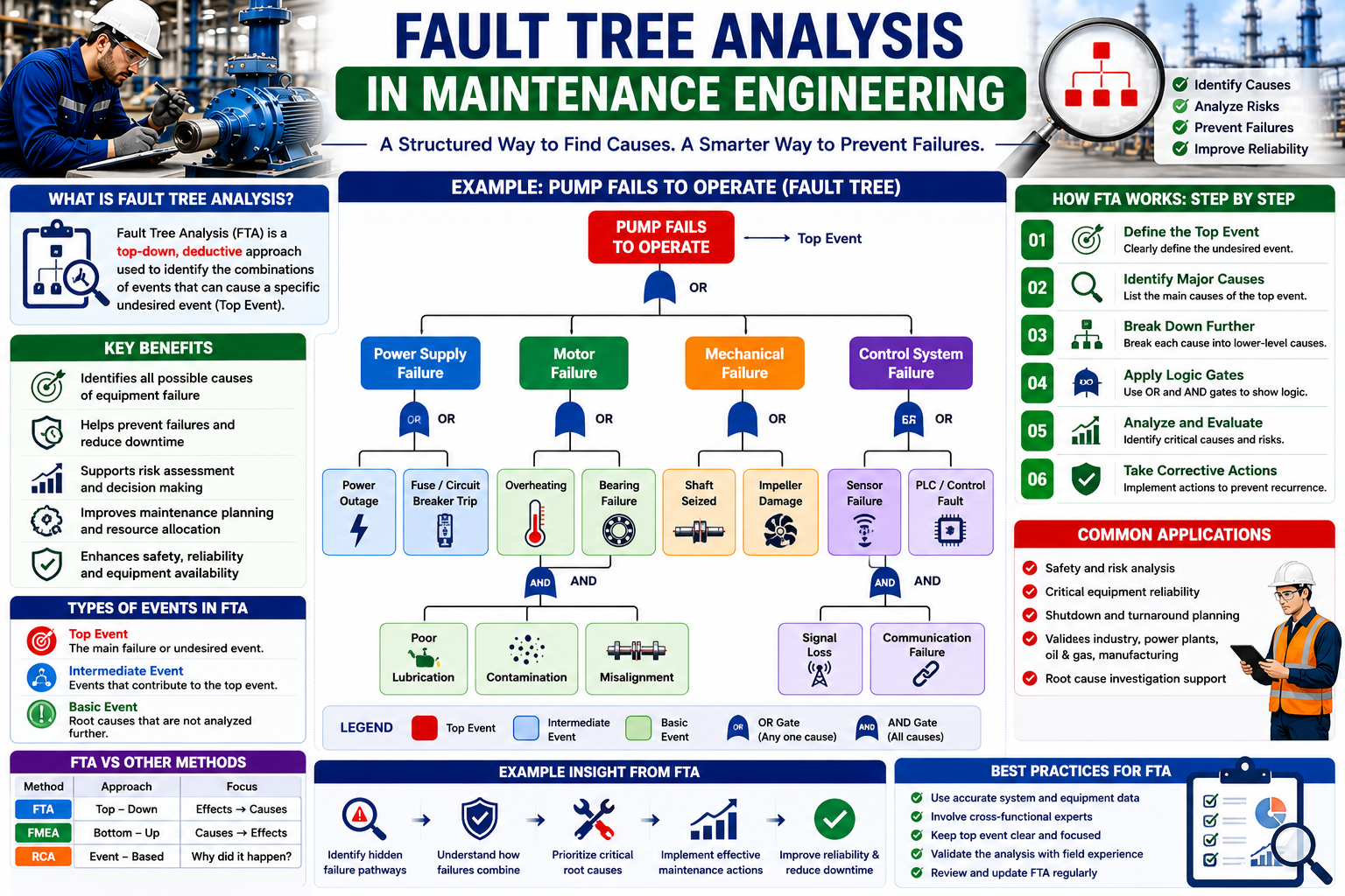
Equipment failures in industrial facilities can have serious consequences. A single failure may stop production, damage equipment, increase maintenance costs, affect product quality, or create safety and environmental risks.
For complex systems, simply looking at the failed component may not be enough to understand why the failure occurred. Maintenance and reliability engineers need structured methods that allow them to investigate how multiple failures, conditions, and human factors can combine to create an unwanted event.
Fault Tree Analysis (FTA) is one of the most useful techniques for this purpose.
Fault Tree Analysis provides a logical, top-down approach for identifying the possible causes of a specific system failure. It can help maintenance teams understand complex failure relationships, prioritize risks, improve maintenance strategies, and identify opportunities for reliability improvement.
What Is Fault Tree Analysis?
Fault Tree Analysis is a systematic method used to identify and analyze the combinations of events that can lead to a specific unwanted event or system failure.
The unwanted event is placed at the top of the fault tree and is called the top event.
The engineer then works downward to identify possible causes.
For example:
Top Event: Pump fails to operate
Possible causes could include:
Motor failure OR power supply failure OR control-system failure OR mechanical seizure
Each of these causes can then be broken down into more detailed events.
This creates a tree-like logical structure showing how individual failures can combine to produce the top event.
FTA is therefore particularly useful for systems where several different failure pathways can lead to the same consequence.
Why Is Fault Tree Analysis Important in Maintenance?
Traditional troubleshooting often focuses on the immediate cause of a failure.
Fault Tree Analysis encourages engineers to look at the complete chain of events.
For example, if a pump stops, replacing the motor may restore operation.
But why did the motor fail?
Potential causes might include:
- Electrical overload
- Poor cooling
- Bearing failure
- Excessive vibration
- Misalignment
- Insulation deterioration
- Incorrect operating conditions
FTA helps organize these possibilities and determine how different events may contribute to the final failure.
The method can therefore support both failure investigation and failure prevention.
Basic Elements of a Fault Tree
A fault tree consists of several types of events and logical relationships.
Top Event
The top event represents the failure or unwanted event being investigated.
Examples include:
- Production line stops
- Pump fails to start
- Emergency shutdown occurs
- Cooling system fails
- Compressor trips
- Generator fails to produce power
The top event should be clearly defined.
Intermediate Events
Intermediate events are conditions that contribute to the top event but may themselves have underlying causes.
For example:
Pump fails to operate
may result from:
Motor fails OR pump mechanically seized
These are intermediate events.
Basic Events
Basic events are fundamental causes that are not normally broken down further within the scope of the analysis.
Examples include:
- Fuse failure
- Bearing seizure
- Power loss
- Sensor failure
- Operator error
- Cable damage
AND and OR Gates
Logical gates are one of the most important parts of Fault Tree Analysis.
OR Gate
An OR gate means that any one of the input events can cause the output event.
For example:
Pump fails
may occur because:
Motor failure OR power supply failure
If either condition occurs, the pump may fail.
AND Gate
An AND gate means that multiple input events must occur together for the output event to occur.
For example:
Motor overheats
may require:
High mechanical load AND inadequate cooling
Both conditions may need to exist simultaneously for the specific overheating event to occur.
Understanding these logical relationships allows engineers to model complex failure mechanisms.
You may also like: Different Types of Pumps Used in Industry & Home Every Day
Step-by-Step Fault Tree Analysis
Step 1: Define the System
Before beginning the analysis, clearly define the equipment or system being investigated.
Identify:
- Equipment boundaries
- Operating conditions
- Main functions
- Critical components
- Interfaces with other systems
For example, an analysis may focus specifically on a cooling-water pump rather than the entire plant.
Step 2: Define the Top Event
Clearly describe the unwanted event.
A weak definition would be:
Pump problem
A better definition is:
Cooling-water pump fails to deliver the required flow during normal plant operation.
A precise top event keeps the analysis focused.
Step 3: Identify Immediate Causes
Determine the major events that could directly produce the top event.
For example:
Pump fails to deliver flow
could be caused by:
- Pump mechanical failure
- Motor failure
- Electrical supply failure
- Control-system failure
- Process-related condition
These become branches beneath the top event.
Step 4: Break Down Each Cause
Continue asking:
“What could cause this event?”
For example:
Pump mechanical failure
could result from:
- Bearing failure
- Shaft failure
- Impeller damage
- Seal failure
Then:
Bearing failure
could result from:
- Poor lubrication
- Contamination
- Misalignment
- Excessive loading
- Incorrect installation
The tree continues until the causes are sufficiently detailed.
Step 5: Apply Logic Gates
Determine whether causes are connected through AND or OR relationships.
For example:
Bearing failure
could occur through:
Poor lubrication OR contamination OR misalignment
However, a specific overheating event might require:
High load AND inadequate lubrication
These relationships make the analysis more realistic.
Step 6: Validate the Fault Tree
The fault tree should be reviewed with people who understand the equipment.
This may include:
- Maintenance engineers
- Reliability engineers
- Technicians
- Operators
- Electrical engineers
- Instrumentation specialists
- Process engineers
Different specialists may identify failure pathways that others might overlook.
Example of Fault Tree Analysis
Consider a production pump that unexpectedly stops.
The top event is:
Pump stops during operation
The possible branches are:
Branch 1: Motor Failure
Potential causes:
- Bearing failure
- Electrical overload
- Insulation failure
- Overheating
Branch 2: Power Supply Failure
Potential causes:
- Circuit breaker trip
- Cable failure
- Transformer problem
- External power interruption
Branch 3: Control System Failure
Potential causes:
- Faulty sensor
- PLC problem
- Incorrect control signal
- Communication failure
Branch 4: Mechanical Failure
Potential causes:
- Shaft failure
- Coupling failure
- Impeller damage
- Pump seizure
The fault tree provides a visual representation of all these possible pathways.
The maintenance team can then investigate each branch using evidence, historical failure data, inspection results, and condition-monitoring information.
Quantitative Fault Tree Analysis
Fault Tree Analysis can be qualitative or quantitative.
Qualitative FTA
Qualitative analysis focuses on understanding the possible causes and relationships.
It can answer:
- What can cause the failure?
- Which failure pathways exist?
- Which combinations of events are important?
Quantitative FTA
Quantitative analysis assigns probabilities or failure rates to basic events.
This can help estimate the probability of the top event.
For example, if different components have known failure probabilities, engineers can use logical relationships to estimate the likelihood of system failure.
Quantitative FTA is particularly useful for critical systems where risk needs to be measured.
Benefits of Fault Tree Analysis
1. Identifies Multiple Failure Pathways
FTA helps engineers recognize that a single failure can have several possible causes.
2. Supports Root Cause Investigation
It provides a structured framework for investigating complex failures.
3. Improves Reliability
Understanding failure pathways helps engineers develop better corrective and preventive actions.
4. Supports Maintenance Strategy Development
FTA can help determine where preventive, predictive, or condition-based maintenance activities are appropriate.
5. Improves Risk Management
Organizations can identify failure combinations that could produce serious consequences.
6. Supports Critical Equipment Analysis
FTA is especially useful for safety-critical and production-critical systems.
7. Improves Team Understanding
The visual structure of a fault tree allows engineers from different disciplines to discuss failure mechanisms using a common framework.
Fault Tree Analysis vs Root Cause Analysis
FTA and RCA are related but serve different purposes.
Root Cause Analysis is commonly used to investigate why a specific failure occurred.
Fault Tree Analysis is often used to identify all possible causes and combinations that could lead to a defined top event.
For example:
RCA may investigate:
“Why did Pump P-101 fail yesterday?”
FTA may investigate:
“What combinations of failures could cause Pump P-101 to lose its required function?”
The two methods can complement each other.
Fault Tree Analysis vs FMEA
FMEA and FTA approach failures from different directions.
FMEA generally works from components and failure modes toward their effects.
FTA works from an unwanted top event downward toward its possible causes.
In simple terms:
FMEA = Bottom-Up
FTA = Top-Down
Using both methods can provide a more complete understanding of equipment reliability.
Common Fault Tree Analysis Mistakes
Poorly Defined Top Event
If the top event is vague, the entire analysis can become unfocused.
Stopping Too Early
Engineers should continue breaking down causes until they reach useful basic events.
Incorrect Logic Gates
Incorrectly using AND and OR relationships can produce misleading conclusions.
Ignoring Human Factors
Operator actions, maintenance errors, procedures, training, and communication can contribute to failures.
Ignoring Common-Cause Failures
Several components may fail because of the same underlying condition, such as contamination, environmental exposure, or loss of cooling.
Using Assumptions Without Evidence
Where possible, failure relationships should be supported by equipment history, engineering knowledge, testing, or other evidence.
How FTA Supports Preventive and Predictive Maintenance
Fault Tree Analysis can help identify which failure mechanisms deserve monitoring or preventive action.
For example, if the analysis identifies bearing failure as an important pathway, the maintenance team may introduce:
- Vibration monitoring
- Temperature monitoring
- Lubrication inspections
- Oil analysis
- Alignment checks
If electrical overload is identified as a major pathway, engineers may focus on:
- Motor-current monitoring
- Protection settings
- Electrical inspections
- Load monitoring
FTA therefore helps connect failure analysis with maintenance strategy.
Best Practices for Fault Tree Analysis
For effective results:
- Clearly define the system boundary.
- Define the top event precisely.
- Use accurate equipment information.
- Involve multidisciplinary experts.
- Use AND and OR gates correctly.
- Include human and environmental factors.
- Review historical failure data.
- Validate the tree with experienced personnel.
- Prioritize high-risk failure pathways.
- Update the analysis when equipment or operating conditions change.