Heat exchangers are the quiet workhorses of industrial processing. Almost every plant that heats, cools, condenses, or recovers energy from a fluid relies on some form of heat exchanger, and among all the designs available, the shell and tube heat exchanger remains the most widely used across the world. From oil refineries to power plants, from chemical processing units to HVAC systems, this design has earned its place as the industry standard for handling high pressures, high temperatures, and demanding process conditions.
In this guide, we’ll break down everything you need to know about a shell and tube heat exchanger — what it is, how it’s built, how it works, its diagram, pros and cons, and where it’s used in the real world.
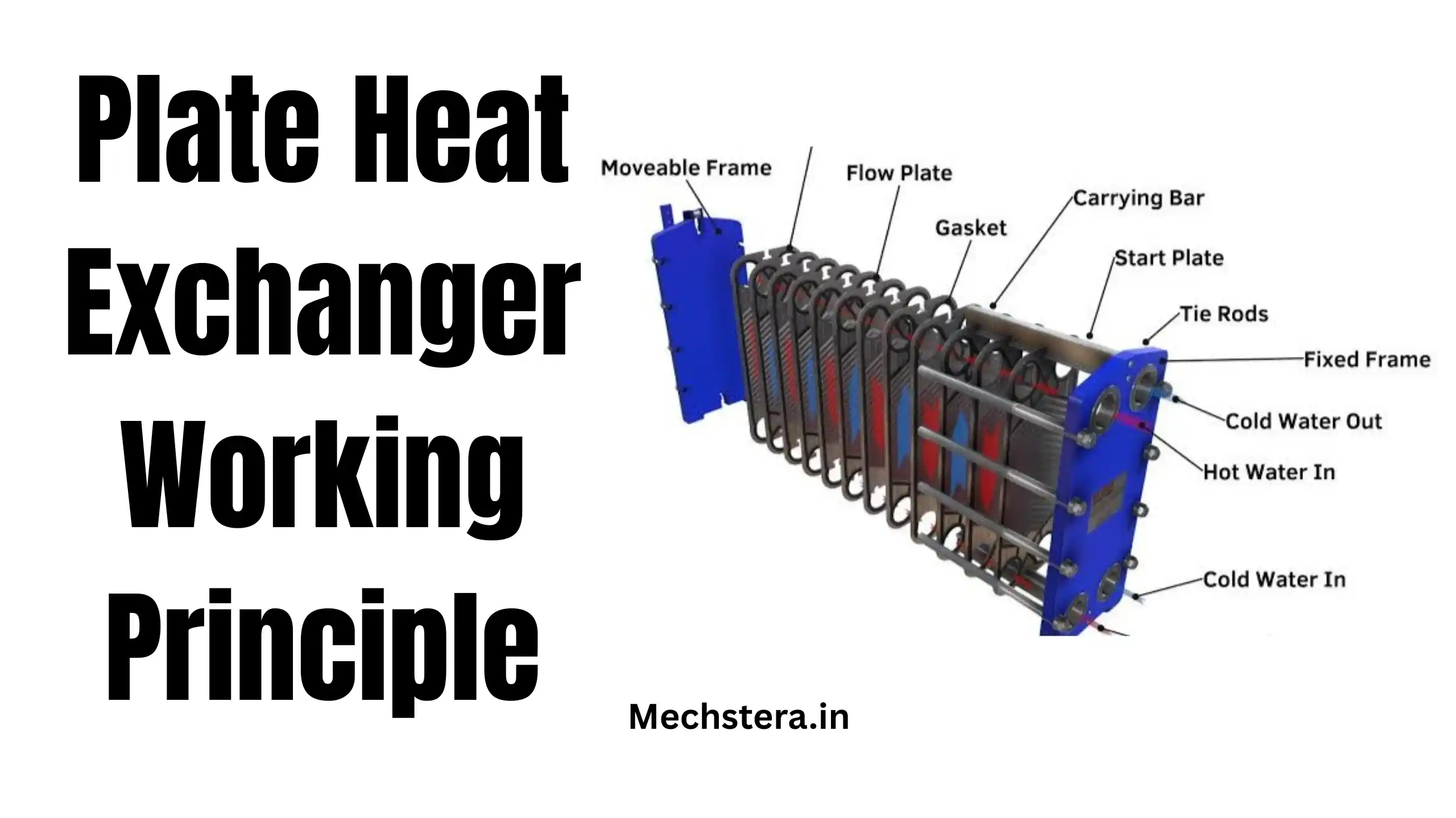
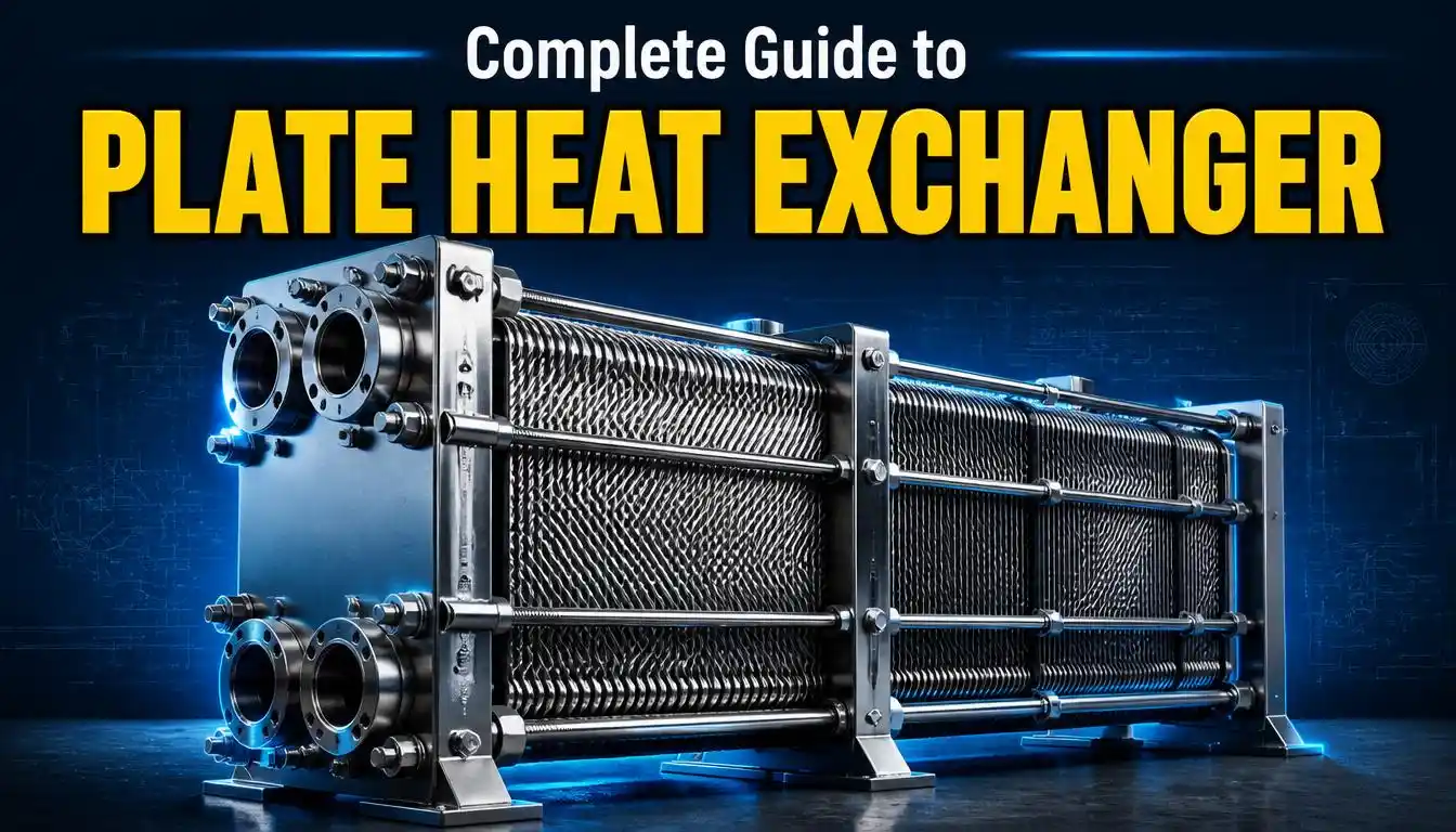
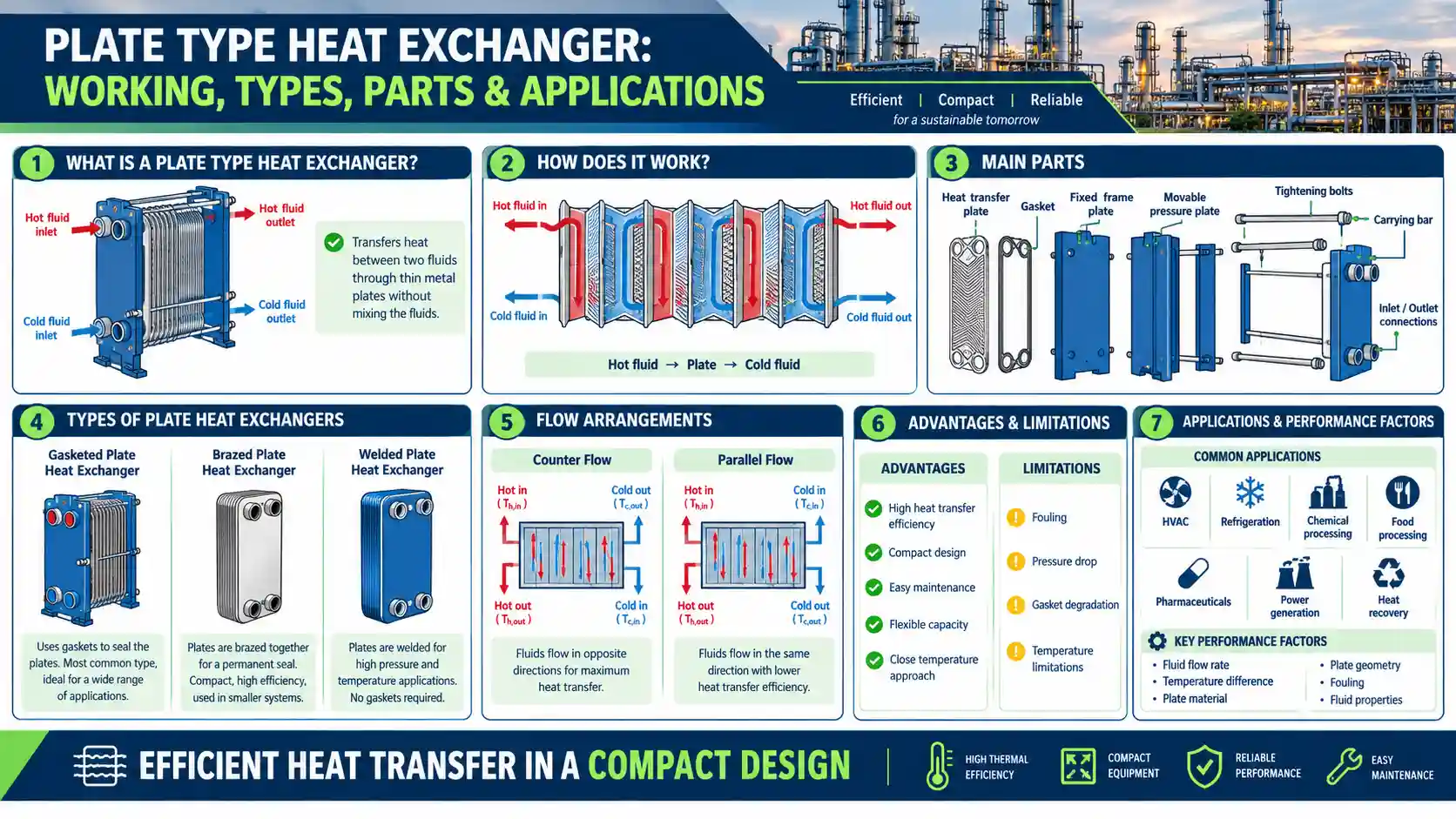
If you’re comparing designs, you may also want to read our guide on the Plate Heat Exchanger to see how it stacks up against the shell and tube design, or explore the different Types of Shell and Tube Heat Exchanger for a deeper dive into TEMA classifications.
What is a Shell and Tube Heat Exchanger?
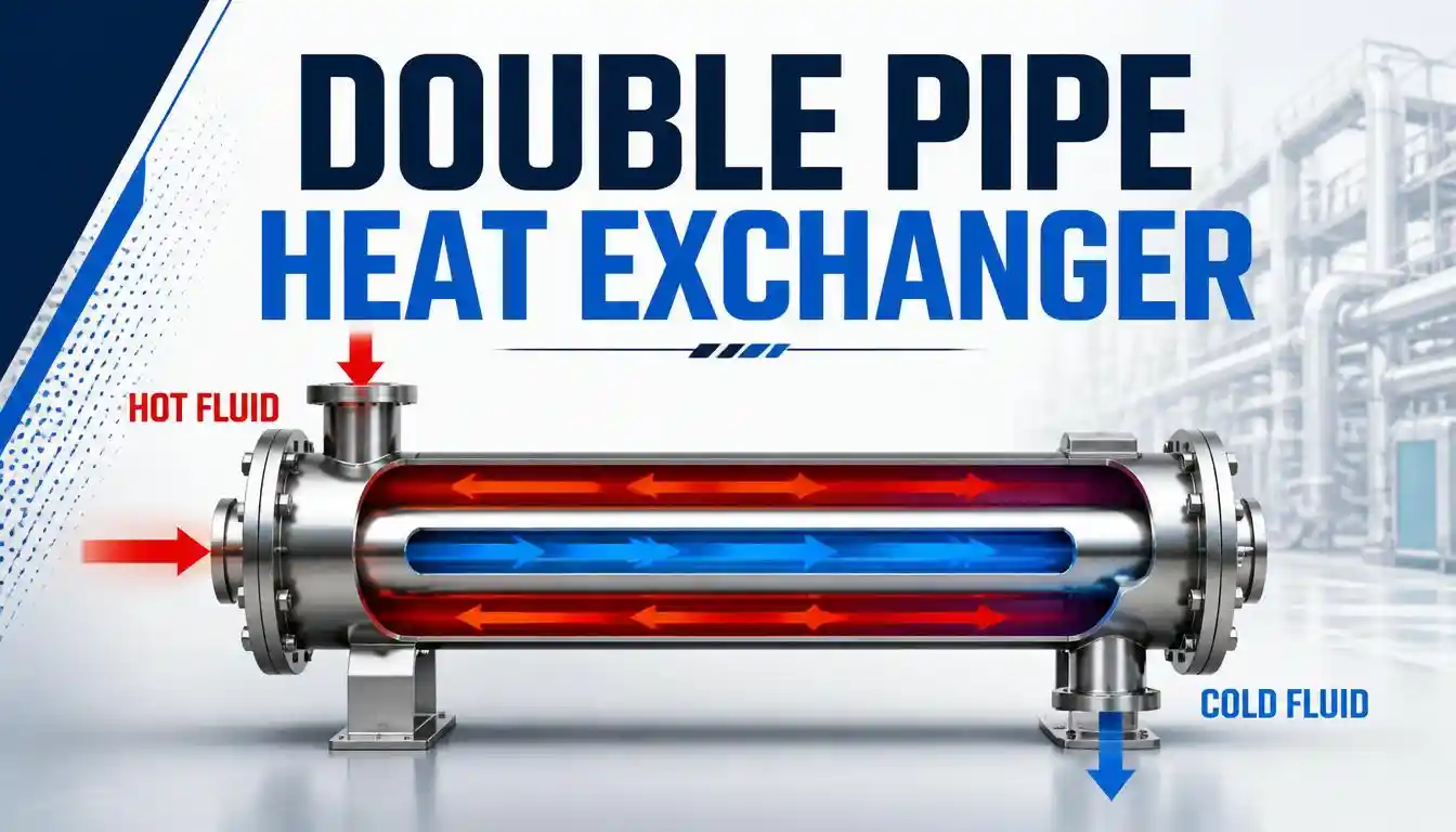
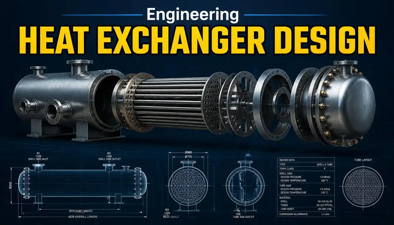
A shell and tube heat exchanger is a type of heat exchanger consisting of a large cylindrical outer vessel, called the shell, which houses a bundle of smaller tubes running through it. One fluid flows through the tubes, while a second fluid flows around the outside of the tubes, within the shell. Heat is transferred between the two fluids through the tube walls, without the fluids ever coming into direct contact with each other.
This indirect transfer of heat is what makes the shell and tube heat exchanger so versatile. Because the two fluids remain physically separated, this tube type heat exchanger can be used to transfer heat between fluids that would otherwise react, contaminate one another, or simply need to stay isolated for process reasons — such as steam and process water, oil and coolant, or corrosive chemicals and clean utility fluids.
The design has been refined over decades and is governed by internationally recognized construction standards published by the Tubular Exchanger Manufacturers Association (TEMA), which define the mechanical design, fabrication tolerances, and testing requirements manufacturers must follow. This standardization is a big reason the shell and tube design is trusted in critical, high-stakes environments like refineries and power stations.
Components of a Shell and Tube Heat Exchanger
Before understanding how the unit works, it helps to know its major components. Every shell and tube heat exchanger, regardless of size or application, is built around these core parts:
1. Shell
The shell is the outer cylindrical vessel that encloses the tube bundle. It’s typically made from carbon steel, stainless steel, or other alloys depending on the fluid being handled and the pressure/temperature conditions.
2. Tube Bundle
This is the collection of tubes through which one of the fluids flows. The number, diameter, and arrangement of tubes determine the surface area available for heat transfer, and therefore the exchanger’s overall capacity.
3. Tube Sheets
Tube sheets are flat plates at each end of the shell that hold the tubes firmly in place and separate the shell-side fluid from the tube-side fluid.
4. Baffles
Baffles are plates installed inside the shell, perpendicular to the tube bundle. They serve two purposes: they support the tubes and prevent sagging or vibration, and they force the shell-side fluid to flow in a zig-zag pattern across the tubes rather than straight through, which significantly improves heat transfer efficiency.
5. Front and Rear Head (Channels)
These are the end sections that direct the tube-side fluid into and out of the tube bundle. Depending on the TEMA type, these can be removable for easy cleaning and maintenance.
6. Nozzles
Nozzles are the inlet and outlet connections through which the two fluids enter and exit the shell and tube sides respectively.
7. Tie Rods and Spacers
These hold the baffles in their correct positions and maintain consistent spacing along the length of the tube bundle.
Construction of a Shell and Tube Heat Exchanger
The construction of a shell and tube heat exchanger begins with selecting the right materials and configuration based on the fluids involved, operating pressure, temperature, and the required heat duty. Tubes are arranged inside the shell in a specific pattern — commonly triangular, square, or rotated square pitch — which affects turbulence, pressure drop, and how easily the unit can be cleaned.
The tube bundle is fixed at both ends using tube sheets, and depending on the application, the exchanger may be built with:
- A fixed tube sheet, where the tube bundle is permanently welded to the shell (simple and economical, but harder to clean on the shell side)
- A U-tube bundle, where tubes are bent into a U-shape, allowing one tube sheet and easier bundle removal
- A floating head, where one end of the tube bundle is free to move, accommodating thermal expansion and allowing full bundle removal for cleaning
Construction also follows the TEMA classification system, which defines exchangers as Class R (severe refinery/petroleum service), Class C (general commercial service), or Class B (chemical process service). Each class specifies different minimum thicknesses, materials, and construction rigor depending on how demanding the service conditions are.
Because fabrication has to account for thermal expansion, corrosion allowance, and mechanical strength simultaneously, shell and tube units are almost always custom-engineered for the specific duty rather than bought off the shelf.
Working Principle of Shell and Tube Heat Exchanger
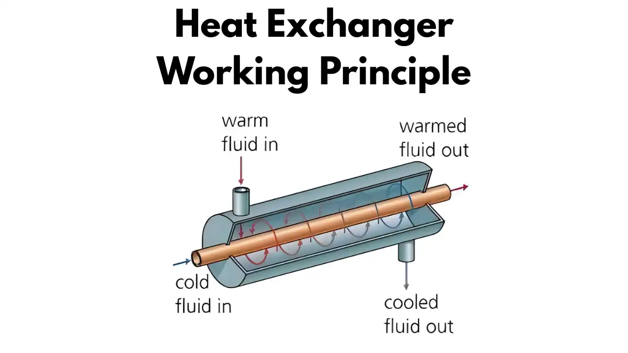
The working principle of a shell and tube heat exchanger is based on simple, well-understood physics: heat naturally flows from a hotter fluid to a cooler one until thermal equilibrium is approached, and this transfer happens through conduction across the tube walls, combined with convection on either side of those walls.
Here’s the shell and tube heat exchanger working, step by step:
- Fluid entry: One fluid (the tube-side fluid) enters through a nozzle and flows through the inside of the tubes. The second fluid (the shell-side fluid) enters the shell and flows around the outside of the same tubes.
- Heat exchange: As the two fluids move past each other — separated only by the thin tube walls — heat transfers from the hotter stream to the cooler stream. The metal tube wall conducts heat, while convection currents in each fluid carry heat toward and away from that wall.
- Baffle-directed flow: Baffles inside the shell force the shell-side fluid into a zig-zag path across the tube bundle, increasing turbulence and contact time, which improves the rate of heat transfer.
- Fluid exit: Once heat has been transferred, both fluids exit through their respective outlet nozzles at their new temperatures — the hot fluid cooler than it entered, and the cold fluid warmer than it entered.
Flow arrangement plays a major role in efficiency. In a shell and tube heat exchanger, fluids can be arranged in:
- Counterflow, where the two fluids move in opposite directions — generally the most thermally efficient arrangement
- Parallel flow (co-current), where both fluids move in the same direction
- Cross flow, where fluid moves perpendicular to the tube bundle, often combined with multiple tube passes for better performance
The working principle of shell and tube heat exchanger designs can also include multiple “passes” — meaning the tube-side fluid travels back and forth through the shell more than once — to extract more heat from a limited shell length.
Shell and Tube Heat Exchanger Diagram
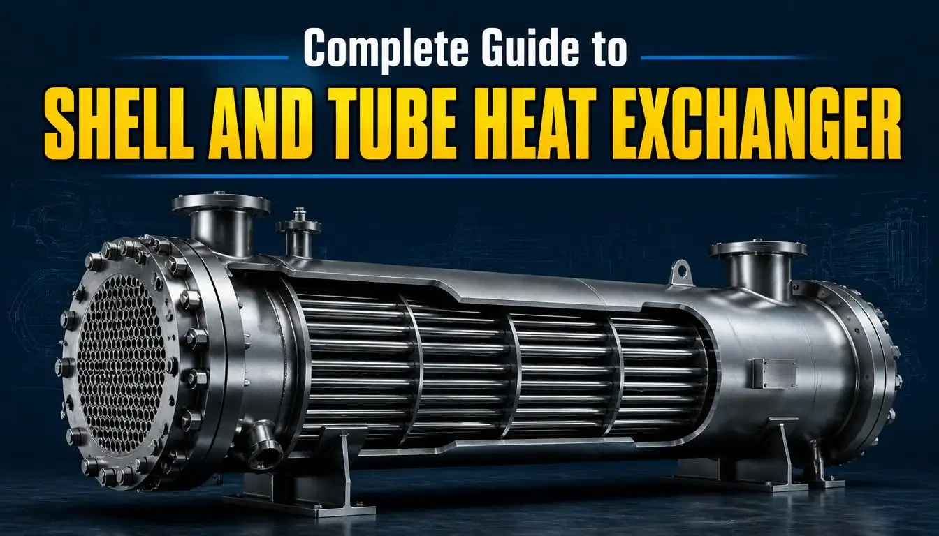
A shell and tube heat exchanger diagram typically shows the cylindrical shell with the tube bundle running through its center, tube sheets capping each end, baffles spaced along the shell interior, and nozzles marking where each fluid enters and exits.
In a standard shell and tube heat exchanger diagram, you’ll usually see:
- The shell-side inlet and outlet nozzles positioned near the top and bottom (or opposite ends) of the shell
- The tube-side inlet and outlet connected to the front and rear heads
- Baffles drawn as segmented plates creating the zig-zag flow path for the shell-side fluid
- Tube sheets shown as end plates anchoring the tube bundle
This visual layout makes it easy to trace both flow paths simultaneously and understand why the design is so effective — the shell-side fluid is forced into constant contact with the tube surfaces as it winds past each baffle, maximizing the heat transfer area used at any given moment.
If you’re specifying or ordering a unit, referencing a proper shell and tube heat exchanger diagram alongside the TEMA nomenclature system helps ensure the front head, shell type, and rear head configurations match your process requirements exactly.
Advantages of Shell and Tube Heat Exchangers
The shell and tube heat exchanger has remained dominant in industry for good reason. Key advantages include:
- High pressure and temperature tolerance: The cylindrical shell design handles high-pressure and high-temperature service far better than many alternative designs, including plate types.
- Robust and durable construction: Built from materials like carbon steel, stainless steel, and various corrosion-resistant alloys, these units are engineered to last for years under demanding conditions.
- Wide range of applications: They can handle liquids, gases, and phase-change processes (evaporation and condensation) with equal reliability.
- Easier maintenance and cleaning: Many designs (especially floating head and U-tube types) allow the tube bundle to be removed for inspection and cleaning.
- Scalability: Capacity can be increased simply by adding more tubes or increasing shell diameter, making the design flexible for different plant sizes.
- Proven, standardized design: Because construction follows TEMA standards, engineers and manufacturers across the globe work from the same design language, simplifying procurement and quality assurance.
Disadvantages of Shell and Tube Heat Exchangers
No design is without trade-offs. Some limitations of shell and tube heat exchangers include:
- Larger footprint: They generally take up more space than compact alternatives like plate heat exchangers for the same heat duty.
- Higher cost for equivalent surface area: Fabrication complexity, especially for high-pressure classes, can make them more expensive per unit of heat transfer area than plate designs.
- Fouling on the shell side: Depending on baffle spacing and flow velocity, the shell side can be prone to fouling and deposit buildup if not properly designed or maintained.
- Difficult to modify after fabrication: Because tube bundles are custom-built for specific duties, adjusting capacity later usually means fabricating a new unit rather than simply adding plates.
- Weight: Larger units, especially those built to Class R specifications, are heavy and require significant structural support during installation.
Applications of Shell and Tube Heat Exchangers
Because of their strength, reliability, and flexibility, shell and tube heat exchangers show up in nearly every heavy industry:
- Oil and gas / refining: Used extensively for crude oil preheating, cooling of refined products, and condensing vapors during distillation and cracking processes.
- Power generation: Found in steam condensers and feedwater heaters, helping recover and reuse thermal energy across the power cycle.
- Chemical and petrochemical processing: Employed for reactor heating/cooling, and for handling corrosive or hazardous fluids where robust construction is essential.
- HVAC systems: Used in chillers and boilers to transfer heat between refrigerants, water, or air in large commercial buildings.
- Marine industry: Used for engine cooling and central cooling systems on ships, where resistance to saltwater corrosion is critical.
- Food and pharmaceutical processing: Used for gentle, even heating or cooling of products where temperature control directly affects product quality.
This broad footprint across multiple industries is exactly why the shell and tube heat exchanger remains the default choice whenever a process demands durability, high-pressure tolerance, and dependable long-term performance.
Shell and Tube Condenser
A shell and tube condenser is a specific application of the shell and tube design, used to convert a vapor into a liquid by removing latent heat — most commonly seen in power plant steam condensers and refrigeration systems.
In a typical shell and tube condenser, vapor (often steam) enters the shell side and flows over a bundle of tubes carrying a cooling fluid, usually water. As the vapor contacts the cooler tube surfaces, it loses heat and condenses into liquid, which then collects at the bottom of the shell and is drained away. Because condensation involves a phase change, shell and tube condensers are specifically designed to accommodate the volume difference between vapor and liquid, often using larger shell diameters or specialized baffle spacing on the vapor side.
Shell and tube condensers are essential in:
- Steam power plants, where they convert exhaust steam from turbines back into water for reuse in the boiler cycle
- Refrigeration and HVAC systems, where they condense refrigerant vapor after compression
- Chemical processing, where they recover solvent vapors or condense process gases
Their reliability under high vacuum and large vapor volumes makes them a preferred choice wherever large-scale condensation is required. For a broader look at how condenser design compares with other exchanger types, resources like Engineering-focused overviews of shell and tube design are a useful reference point.
FAQs
1. What is a shell and tube heat exchanger used for?
It’s used to transfer heat between two fluids without letting them mix — commonly for heating, cooling, condensing, or evaporating fluids in industries like oil and gas, power generation, chemical processing, and HVAC.
2. What is the working principle of a shell and tube heat exchanger?
Heat transfers from the hotter fluid to the cooler fluid through the tube walls by conduction, while baffles direct the shell-side fluid across the tube bundle to maximize contact and improve heat transfer efficiency.
3. What is the difference between a shell and tube heat exchanger and a plate heat exchanger?
Shell and tube designs handle higher pressures and temperatures and are more robust for heavy industrial use, while plate heat exchangers are more compact and efficient for lower-pressure, space-constrained applications. See our detailed comparison in the Plate Heat Exchanger guide.
4. What are the main types of shell and tube heat exchangers?
Common types include fixed tube sheet, U-tube, and floating head designs, each suited to different maintenance needs and thermal expansion requirements. Explore these in depth in our Types of Shell and Tube Heat Exchanger article.
5. Why are baffles used in a shell and tube heat exchanger?
Baffles support the tube bundle, reduce vibration, and force the shell-side fluid into a zig-zag flow path, which increases turbulence and significantly improves heat transfer performance.
6. What materials are shell and tube heat exchangers made from?
Common materials include carbon steel, stainless steel, titanium, and copper alloys, chosen based on the fluid’s corrosiveness, operating pressure, and temperature.
7. How is a shell and tube heat exchanger cleaned?
Depending on the design, the tube bundle can often be removed for mechanical cleaning, or the unit can be chemically cleaned in place, especially for fixed tube sheet designs where bundle removal isn’t possible.