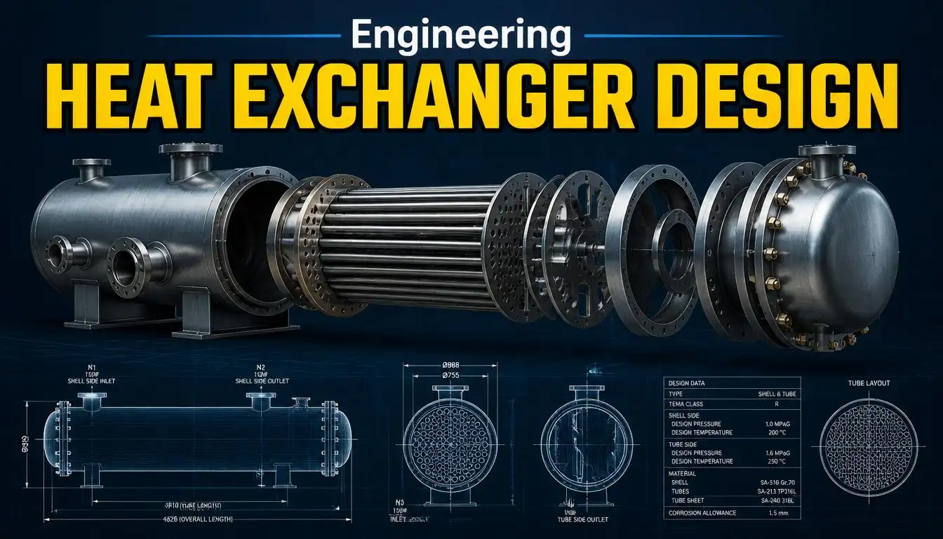
Heat exchanger design is one of the most critical disciplines in process and mechanical engineering. Whether you’re working on a petrochemical plant, an HVAC system, or a power generation unit, the ability to correctly design a shell and tube heat exchanger determines how efficiently thermal energy transfers between fluids — and how safely and economically your equipment performs over its lifetime.
This guide walks through the complete process of heat exchanger design, from selecting the right configuration to performing detailed shell and tube heat exchanger design calculations. Whether you’re a student learning the fundamentals or a practicing engineer refining your design of heat exchanger calculations, this article covers everything you need.
What Is Heat Exchanger Design?
Heat exchanger design is the engineering process of sizing and configuring equipment that transfers heat between two or more fluids without mixing them. The goal is to achieve the required heat duty while minimizing pressure drop, material cost, and physical footprint.
A well-executed heat exchanger design balances several competing factors:
- Thermal performance (heat transfer rate)
- Pressure drop on both fluid sides
- Mechanical strength and fabrication cost
- Fouling resistance and maintenance access
- Compliance with industry codes such as TEMA standards and ASME Section VIII
Among all exchanger types, the shell and tube heat exchanger remains the most widely used in industrial applications due to its robustness, flexibility, and ability to handle high pressures and temperatures.
Why Shell and Tube Heat Exchangers Dominate Industrial Design
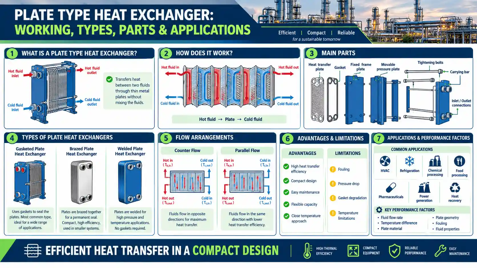
If you search for “heat exchanger design,” most engineering discussions inevitably lead to shell and tube configurations. This design consists of a bundle of tubes enclosed within a cylindrical shell. One fluid flows through the tubes while the other flows around them within the shell, promoting efficient heat exchange.
According to the Engineering ToolBox, shell and tube exchangers are favored in industries such as oil refining, power generation, and chemical processing because they can be custom-built to handle a wide range of pressures, temperatures, and fluid types — something plate or air-cooled exchangers often cannot match at scale.
Key Components of a Shell and Tube Heat Exchanger
- Shell – the outer cylindrical vessel housing the tube bundle
- Tube bundle – the set of tubes through which the process fluid flows
- Tube sheets – plates that hold tube ends in place and separate fluid zones
- Baffles – plates that direct shell-side flow and support tubes
- Channel/head – end sections directing fluid into and out of tubes
- Nozzles – inlet and outlet connections for both fluids
Understanding these components is the foundation before you begin any design of shell and tube heat exchanger project.
Step-by-Step Process: How to Design a Shell and Tube Heat Exchanger
Designing a shell and tube heat exchanger typically follows a structured sequence. Below is the standard workflow used by process engineers.
Step 1: Define Process Requirements
Before any heat exchanger tube design work begins, gather the following data:
- Hot and cold fluid flow rates
- Inlet and outlet temperatures for both streams
- Fluid properties (density, viscosity, specific heat, thermal conductivity)
- Allowable pressure drop
- Fouling factors expected in service
- Operating pressure and phase (liquid, vapor, or mixed)
Step 2: Calculate the Heat Duty (Q)
The heat duty is the total thermal energy that must be transferred:
Q = m × Cp × ΔT
Where:
- Q = heat duty (kW or Btu/hr)
- m = mass flow rate
- Cp = specific heat capacity
- ΔT = temperature change of the fluid
This calculation is the starting point of every design of heat exchanger calculations exercise, since all subsequent sizing depends on it.
Step 3: Determine the Log Mean Temperature Difference (LMTD)
Since temperature differences vary along the exchanger length, the Log Mean Temperature Difference (LMTD) is used instead of a simple arithmetic average:
LMTD = (ΔT1 − ΔT2) / ln(ΔT1 / ΔT2)
For multi-pass shell and tube heat exchanger design, a correction factor (F) is applied to account for flow arrangement deviations from true counter-current flow. The Chemical Engineering Handbook resources on LMTD correction provide detailed correction charts for various tube pass configurations.
Step 4: Estimate the Overall Heat Transfer Coefficient (U)
The overall heat transfer coefficient accounts for resistances on both the tube side and shell side, plus fouling and wall conduction resistance:
1/U = 1/hi + Rfi + (t/k) + Rfo + 1/ho
Where:
- hi, ho = inside and outside film coefficients
- Rfi, Rfo = fouling resistances
- t/k = tube wall resistance
Typical U values for common fluid combinations are tabulated in most heat transfer textbooks and design handbooks, and serve as a good starting estimate before detailed correlation-based calculation.
Step 5: Calculate Required Heat Transfer Area
Using the fundamental heat transfer equation:
A = Q / (U × LMTD × F)
This gives the required surface area, which then determines the number of tubes, tube length, and shell diameter needed.
Step 6: Select Tube Size, Layout, and Pitch
Standard tube outer diameters range from 3/4″ to 1.5″, with common lengths of 8, 12, 16, or 20 feet. Tube layout patterns include:
- Triangular pitch (30°) – higher tube density, better heat transfer
- Square pitch (90°) – easier mechanical cleaning
- Rotated square pitch (45°)
The TEMA (Tubular Exchanger Manufacturers Association) standards specify tube pitch ratios, minimum clearances, and construction classes (Class R, C, and B) depending on service severity.
Step 7: Determine Shell Diameter and Baffle Spacing
Once tube count and layout are fixed, shell diameter is calculated using tube bundle diagrams or Kern’s method. Baffle spacing affects shell-side velocity and pressure drop — closer spacing increases turbulence and heat transfer but also increases pressure drop and pumping costs.
Step 8: Perform Pressure Drop Calculations
Both tube-side and shell-side pressure drops must be checked against allowable limits. Excessive pressure drop increases pumping costs, while too little pressure drop may indicate an oversized, inefficient design. The Kern method and Bell-Delaware method are two widely used approaches for shell-side pressure drop estimation, with Bell-Delaware offering higher accuracy for complex baffle geometries.
Step 9: Mechanical and Structural Verification
After thermal-hydraulic sizing, mechanical design ensures the exchanger can withstand operating pressures and thermal stresses. This includes tube sheet thickness calculations, shell wall thickness per ASME Section VIII, and expansion joint requirements if large temperature differentials exist between shell and tubes.
Step 10: Validate with Simulation Software
Modern shell and tube heat exchanger design is rarely done entirely by hand. Software tools such as HTRI Xchanger Suite, Aspen Exchanger Design and Rating (EDR), and CHEMCAD are industry standards for validating manual calculations and optimizing designs. The HTRI research organization provides widely referenced correlations used across the industry for both shell-side and tube-side calculations.
Common Design Configurations
When engineers discuss designing a shell and tube heat exchanger, several configuration variables come into play:
| Configuration | Description | Typical Use Case |
|---|---|---|
| 1-1 (single pass) | One shell pass, one tube pass | Simple, low-cost applications |
| 1-2 | One shell pass, two tube passes | Common general-purpose design |
| 2-4 | Two shell passes, four tube passes | Close temperature approach needs |
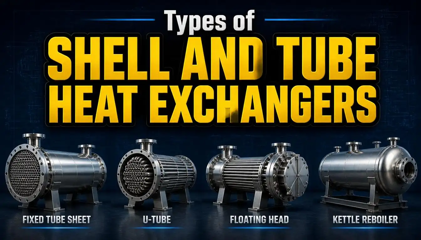
| U-tube | Tubes bent in U-shape | Allows thermal expansion, easy bundle removal |
| Fixed tube sheet | Tubes welded at both ends | Lower cost, limited to smaller ΔT between shell/tube |
| Floating head | One tube sheet free to move | High-temperature differential services |
Key Factors That Influence Heat Exchanger Tube Design
- Fluid velocity – Higher velocity improves heat transfer but increases erosion risk and pressure drop.
- Fouling tendency – Dirty fluids require larger fouling margins and easier-to-clean layouts (square pitch, removable bundles).
- Corrosion allowance – Material selection (carbon steel, stainless steel, titanium, etc.) depends on fluid corrosivity.
- Thermal expansion – Large temperature differences between shell and tube require expansion joints or floating head designs.
- Vibration risk – Long unsupported tube spans in high-velocity shell-side flow can cause tube vibration and fatigue failure, which baffle spacing helps mitigate.
Common Mistakes in Heat Exchanger Design
- Ignoring fouling factors – leads to undersized exchangers that underperform after months of operation.
- Overlooking pressure drop limits – causes excessive pumping costs or pump/compressor incapability.
- Incorrect LMTD correction factor – produces inaccurate area estimates for multi-pass units.
- Poor material selection – results in premature corrosion or failure.
- Skipping vibration analysis – can cause long-term tube bundle damage in high-velocity services.
Manual Calculation vs. Software-Based Design
While understanding the manual design of heat exchanger calculations builds essential engineering intuition, real-world projects almost always rely on simulation software for final designs. Manual methods like Kern’s method are excellent for preliminary sizing and educational purposes, while rating software incorporates proprietary correlations validated against thousands of real exchanger performance data points.
That said, engineers should never treat software as a black box. Understanding the underlying shell and tube heat exchanger design principles — heat duty, LMTD, overall heat transfer coefficient, and pressure drop — is essential to sanity-check software output and troubleshoot underperforming units in the field.
Frequently Asked Questions
What is the basic formula used in heat exchanger design?
The core formula is Q = U × A × LMTD × F, linking heat duty, overall heat transfer coefficient, surface area, and temperature driving force.
What standards govern shell and tube heat exchanger design?
The most widely referenced standards are TEMA (Tubular Exchanger Manufacturers Association) for mechanical and thermal design classes, and ASME Section VIII for pressure vessel construction.
Which software is best for heat exchanger design?
HTRI Xchanger Suite and Aspen EDR are considered industry standards, while CHEMCAD and other process simulators also include heat exchanger rating modules.
What is the difference between fixed tube sheet and floating head designs?
Fixed tube sheet designs are lower cost but limited in handling thermal expansion, while floating head designs allow one tube sheet to move freely, accommodating larger temperature differentials and enabling full bundle removal for cleaning.
Conclusion
Mastering heat exchanger design — particularly shell and tube heat exchanger design — requires a solid grasp of thermodynamics, fluid mechanics, and mechanical engineering principles working together. From calculating heat duty and LMTD to selecting tube layout and validating with simulation software, each step plays a role in creating equipment that performs reliably for decades.
Whether you’re completing your first design of shell and tube heat exchanger as a student or refining production units as a process engineer, following a structured, standards-compliant approach ensures your equipment meets performance targets while remaining cost-effective and maintainable.