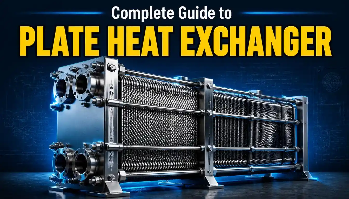
Heat transfer efficiency plays a decisive role in the performance of almost every industrial process — from dairy pasteurization to HVAC systems and chemical processing. Among the many heat transfer technologies available today, the plate heat exchanger stands out for its compact design, high thermal efficiency, and flexibility across a wide range of applications.
If you’ve ever searched for a plate type heat exchanger, come across the term PHE heat exchanger, or wondered how a heat exchanger plate actually moves heat from one fluid to another, this guide covers everything you need to know — components, working principle, diagrams, types, advantages, disadvantages, applications, and a detailed comparison with shell and tube heat exchangers.
What is a Plate Heat Exchanger?
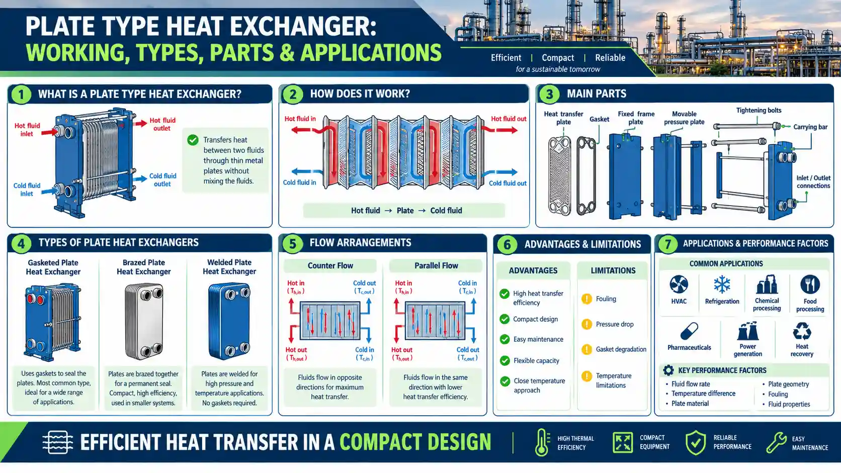
A plate heat exchanger is a type of heat exchanger that uses a series of thin, corrugated metal plates stacked together to transfer heat between two fluids. Unlike traditional tube-based systems, a plate heat exchanger relies on the large surface area created by these plates to move thermal energy efficiently from a hot fluid to a cold fluid — without the two fluids ever mixing.
Each plate is separated by a narrow gap, and gaskets (or brazed/welded joints, depending on the design) direct the two fluids into alternating channels. As the fluids pass through these channels in opposite directions, heat is conducted through the plate walls, allowing one fluid to be heated while the other is cooled.
Plate heat exchangers were first introduced commercially in the 1920s and have since become one of the most widely used heat transfer technologies across industries such as HVAC, food and beverage processing, dairy, pharmaceuticals, marine engineering, and chemical processing, largely because they combine high performance with a relatively small equipment footprint, as Onda explains in its overview of plate heat exchanger design.
In simple terms, if you need to heat or cool a liquid efficiently without a large or bulky system, a plate type heat exchanger is often the go-to solution.
Components of a Plate Heat Exchanger
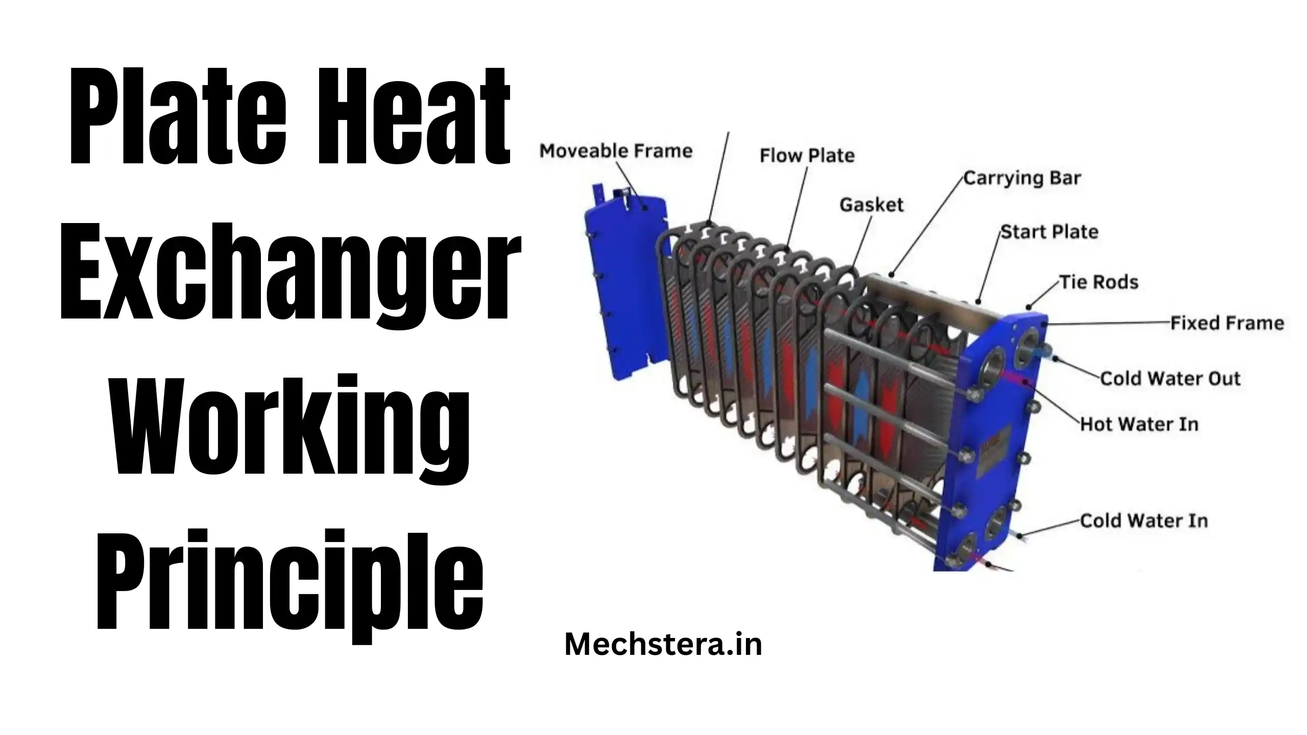
Understanding the individual parts of a plate heat exchanger makes it much easier to grasp how the entire system works. While designs vary slightly between manufacturers, most plate heat exchangers share the following core components:
1. Heat Exchanger Plates
These are the thin, corrugated metal sheets that form the heart of the system. Each heat exchanger plate is typically made from stainless steel, titanium, or other corrosion-resistant alloys, chosen based on the fluids being processed. The corrugation pattern isn’t just for structural strength — it plays a critical role in performance too.
2. Gaskets
Gaskets are fitted around the edges and port holes of each plate to seal the flow channels and direct fluids into the correct path. They also prevent the hot and cold fluids from mixing. Gasketed designs allow the unit to be disassembled for cleaning and maintenance.
3. Frame and Carrying Bar
The frame holds the entire plate pack together. Plates hang from a carrying bar, and a guide bar at the bottom keeps them properly aligned when the unit is opened for maintenance.
4. Clamping Bolts (Tightening Bolts)
These bolts compress the plate pack tightly together, ensuring the gap — or “clearance” — between plates remains small and consistent. This tight clearance is essential for good thermal contact and efficient heat transfer.
5. Inlet and Outlet Nozzles (Ports)
Located at the corners of the frame, these ports allow the hot and cold fluids to enter and exit the exchanger. Proper port placement ensures fluids are distributed evenly across all plates.
6. Fixed and Movable End Covers
The fixed cover stays stationary and usually houses the connection ports, while the movable cover (or pressure plate) can be shifted to open the unit for inspection or plate replacement.
Each of these components works together to form a compact, high-efficiency thermal system — and the specific configuration of plates and gaskets is what defines the different plate heat exchanger types discussed later in this guide.
Working Principle of a Plate Heat Exchanger
The working principle of a plate heat exchanger is based on indirect heat transfer through thin metal plates. Here’s how it works step by step:
- Fluid Entry: Two fluids — one hot and one cold — enter the heat exchanger through separate inlet ports.
- Channel Distribution: The fluids are directed into alternating channels formed between the stacked plates. So, a hot fluid channel is always sandwiched between two cold fluid channels (and vice versa).
- Heat Transfer Through the Plate: As the fluids flow through their respective channels, heat is conducted through the plate wall from the hot fluid to the cold fluid. The two fluids never physically touch or mix — they simply exchange thermal energy across the plate surface.
- Turbulent Flow: The corrugated pattern on each plate forces the fluid into a turbulent flow rather than a smooth, laminar flow. This constant turbulence increases contact with the plate surface and significantly boosts the heat transfer rate while also helping to reduce fouling and scale buildup, a point emphasized in Experphe’s breakdown of plate heat exchanger operation.
- Counter-Current Flow: Most plate heat exchangers use a counter-flow arrangement, meaning the hot and cold fluids move in opposite directions. This maximizes the temperature difference across the length of the plate and results in more efficient heat exchange compared to parallel flow designs.
- Fluid Exit: Once heat exchange is complete, the now-cooled hot fluid and the now-heated cold fluid exit through their respective outlet ports.
This same plate and frame heat exchanger working principle applies whether you’re dealing with a small gasketed unit cooling hydraulic oil or a large brazed unit handling district heating loads. The scale changes, but the fundamental science of turbulent, counter-current heat exchange through thin metal plates remains the same.
According to Alfa Laval’s technical explanation of heat exchanger theory, heat always moves from the hotter medium to the colder one, and the amount of heat lost by the hot fluid always equals the amount gained by the cold fluid — a principle that governs the entire design and sizing of plate heat exchangers.
Plate Heat Exchanger Diagram
A plate heat exchanger diagram is essential for understanding flow direction, plate arrangement, and where maintenance access points are located. While the visual layout can vary depending on manufacturer and application, a typical plate type heat exchanger diagram includes the following elements:
- Fixed frame plate on one end and a movable pressure plate on the other
- A stack of corrugated plates in between, each separated by gaskets
- Four corner ports — two for the hot fluid inlet/outlet and two for the cold fluid inlet/outlet
- Arrows indicating flow direction, typically showing the hot fluid moving downward while the cold fluid moves upward (or vice versa), illustrating the counter-flow arrangement
- Clamping bolts running the length of the frame to hold the plate pack under compression
A well-drawn plate and frame heat exchanger diagram also typically shows a cross-sectional cutaway, revealing how alternating channels are formed and how each plate contacts both a hot and a cold channel simultaneously — one on each face. This cutaway view is often the clearest way to visualize why plate heat exchangers achieve such high thermal efficiency compared to older exchanger designs: every single plate surface is actively participating in heat transfer, not just a small tube wall.
Engineers and technicians rely on these diagrams not just for understanding function, but for practical purposes too — installation planning, troubleshooting, plate replacement, and gasket inspection all depend on an accurate diagram of the internal flow path.
Plate Heat Exchanger Types
Not all plate heat exchangers are built the same way. Depending on the application, pressure requirements, fluid type, and maintenance needs, there are several distinct plate heat exchanger types to choose from.
1. Gasketed Plate Heat Exchanger
This is the most common and widely recognized type. Plates are separated by rubber gaskets and held together with clamping bolts, allowing the unit to be opened for cleaning, inspection, or adding/removing plates to adjust capacity. Gasketed units are popular in food processing, HVAC, and industrial cooling because of their serviceability.
2. Brazed Plate Heat Exchanger (BPHE)
In a brazed plate heat exchanger, the plates are fused together using a brazing material (typically copper or nickel) instead of gaskets. This creates a compact, sealed, and highly durable unit capable of handling higher pressures and temperatures than gasketed models. However, since they can’t be disassembled, they aren’t suitable for fluids prone to heavy fouling.
3. Welded Plate Heat Exchanger
Welded units offer a middle ground — some or all of the plate joints are welded rather than gasketed, allowing them to handle more aggressive fluids, higher pressures, and higher temperatures while still permitting partial disassembly in semi-welded designs.
4. Wide-Gap Plate Heat Exchanger
Designed with a larger gap between plates, this type is used for fluids containing fibers, particles, or viscous components — such as in pulp and paper processing or wastewater treatment — where a standard tight-clearance design would clog easily.
5. Double-Wall Plate Heat Exchanger
Used when cross-contamination between fluids must be absolutely avoided (such as in certain pharmaceutical or chemical applications), double-wall plates add an extra layer of protection. If one plate develops a leak, the second wall prevents fluid mixing.
Understanding these different types of plate heat exchanger designs helps engineers and procurement teams select the right unit based on fluid characteristics, pressure/temperature range, and maintenance expectations — rather than assuming a single “one size fits all” solution.
Plate and Frame Heat Exchanger
The term “plate and frame heat exchanger” is often used interchangeably with “gasketed plate heat exchanger,” and for good reason — it’s the most classic and adaptable configuration in the plate heat exchanger family.
In a plate and frame heat exchanger, the plates are mounted between a fixed frame and a movable frame, compressed together with tightening bolts. This construction offers a major practical advantage: capacity can be increased or decreased simply by adding or removing plates, without needing to replace the entire unit. This scalability makes plate and frame units especially attractive for facilities anticipating future capacity changes or seasonal variation in thermal load.
The plate and frame heat exchanger working principle follows the same counter-current, turbulent-flow logic described earlier, but the modular frame design is what sets it apart operationally. Maintenance teams can open the frame, inspect each plate individually, replace damaged gaskets, and reassemble the unit — all without specialized welding or brazing equipment on site.
This flexibility is a major reason plate and frame heat exchangers dominate industries like dairy processing, brewing, HVAC, and district heating, where periodic cleaning and inspection are non-negotiable for hygiene or performance reasons.
Advantages of Plate Heat Exchangers
Plate heat exchangers have earned their popularity across industries for several well-documented reasons:
- High Thermal Efficiency: The large surface area and turbulent flow pattern allow plate heat exchangers to achieve significantly higher heat transfer coefficients than shell and tube designs — often several times more efficient for the same footprint.
- Compact Footprint: Because the plates are stacked closely together, plate heat exchangers require far less installation space than traditional shell and tube systems, making them ideal for facilities with limited floor space.
- Easy Maintenance and Cleaning: Gasketed models can be opened easily for inspection, cleaning, and gasket replacement — no specialized tools required.
- Scalability: Capacity can be adjusted by simply adding or removing plates, without replacing the entire unit.
- Lower Fluid Volume: The narrow channels mean less fluid is held within the system at any given time, allowing for faster response to changes in process conditions and tighter temperature control.
- Energy Savings: Many plate heat exchangers don’t require insulation to the same degree as shell and tube systems, since heat loss is minimized by design, contributing to lower operating costs over time.
- Reduced Fouling: The turbulent flow pattern created by plate corrugations helps minimize the buildup of scale and deposits compared to more stagnant flow zones in tube-based designs.
Disadvantages of Plate Heat Exchangers
Despite their many benefits, plate heat exchangers aren’t the right fit for every application. Some limitations to consider include:
- Pressure and Temperature Limits: Standard gasketed plate heat exchangers typically aren’t suited for extremely high pressures or temperatures. Gasket materials can begin to degrade above certain temperature thresholds, though specialized gasket materials and welded/brazed designs can extend this range.
- Not Ideal for Highly Viscous or Fibrous Fluids: Standard narrow-gap designs can clog easily with fluids containing particles, fibers, or high viscosity, unless a wide-gap variant is used.
- Gasket Maintenance: While gaskets make cleaning easy, they also require periodic replacement and are a potential point of leakage if not properly maintained.
- Higher Pressure Drop: The turbulence that makes plate heat exchangers so thermally efficient also causes a higher pressure drop compared to shell and tube designs, which can mean higher pumping costs in some systems, a trade-off explained well in CSI Designs’ comparison of plate and shell-and-tube performance.
- Initial Cost for Specialized Materials: For corrosive or high-purity applications requiring titanium or exotic alloy plates, upfront costs can be higher than simpler tube-based alternatives.
Applications of Plate Heat Exchangers
Because of their compact size and excellent thermal efficiency, plate heat exchangers are used across a wide variety of industries, including:
- HVAC Systems: Used in district heating and cooling networks, chillers, and building climate control systems.
- Food and Beverage Processing: Pasteurization, sterilization, and cooling processes for dairy, juices, and brewing applications, where hygienic gasketed designs allow for frequent cleaning.
- Chemical Processing: Heating and cooling of process fluids, often requiring corrosion-resistant plate materials.
- Marine and Offshore Engineering: Compact size makes plate heat exchangers ideal for engine cooling and other thermal management needs on ships and offshore platforms where space is at a premium.
- Power Generation: Used in cooling systems for turbines, generators, and auxiliary equipment.
- Pharmaceutical Manufacturing: Precise temperature control for sensitive processes, sometimes using double-wall plate designs to prevent cross-contamination.
- Refrigeration: Brazed plate heat exchangers are widely used as evaporators and condensers in refrigeration and heat pump systems.
This versatility across such different industries is a direct result of the variety of plate heat exchanger types available — there’s almost always a configuration suited to a specific fluid, pressure, and hygiene requirement.
Plate Heat Exchanger vs Shell and Tube Heat Exchanger
One of the most common decisions engineers face is choosing between a plate heat exchanger and a shell and tube heat exchanger. Both accomplish the same basic goal — transferring heat between two fluids — but they do so in fundamentally different ways, and each comes with its own strengths.
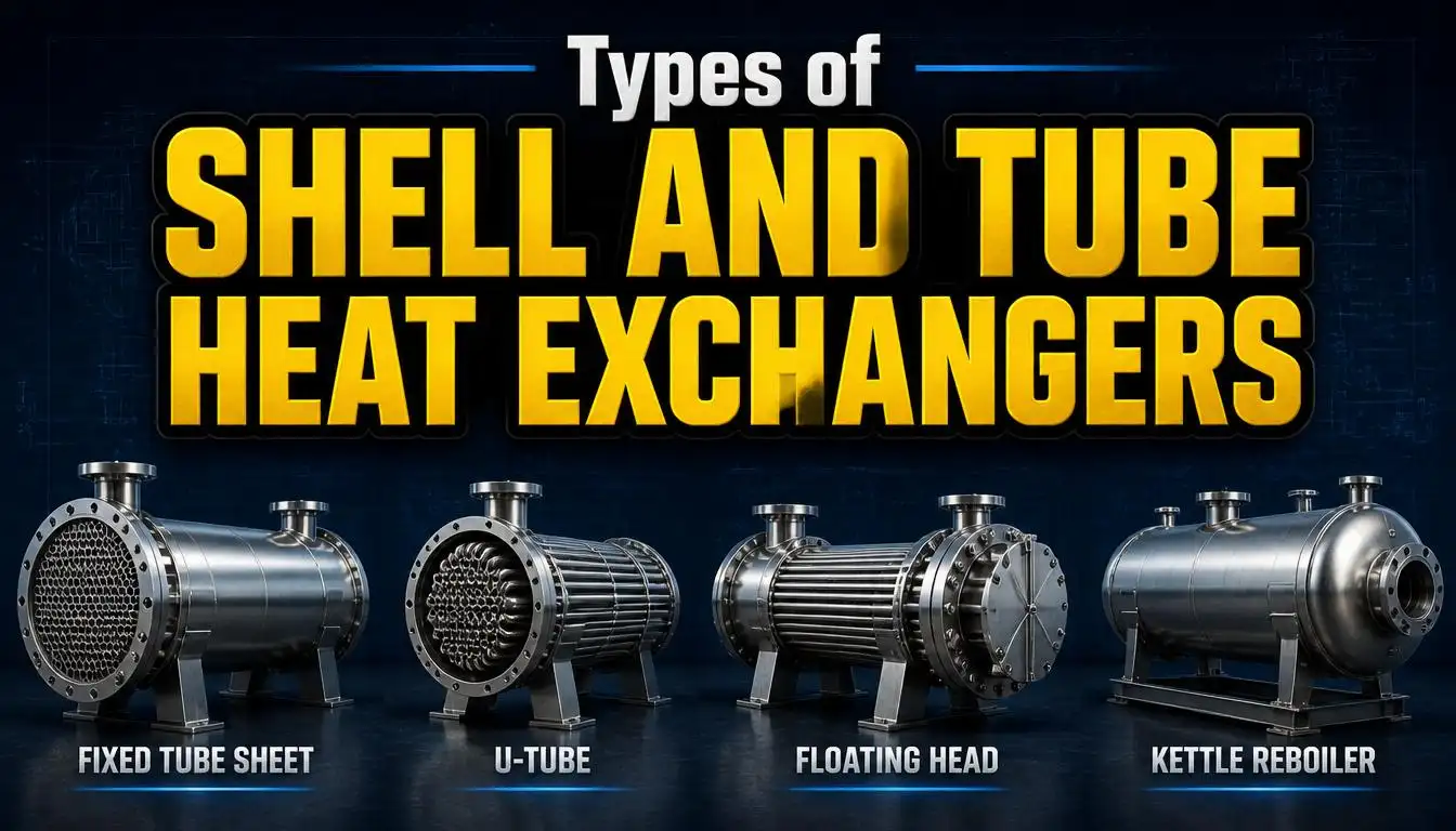
Design: A plate heat exchanger uses stacked, corrugated plates to create alternating flow channels, while a shell and tube heat exchanger uses a bundle of tubes housed inside a cylindrical outer shell, with one fluid flowing through the tubes and the other flowing around them.
Thermal Efficiency: Plate heat exchangers generally offer significantly higher heat transfer efficiency for the same physical size, largely because of their greater surface area to volume ratio and turbulent flow characteristics, as highlighted in Tranter’s comparison of plate and frame versus shell and tube designs.
Footprint: Plate heat exchangers are far more compact and lightweight, making them easier to install, transport, and retrofit into space-constrained facilities. Shell and tube units require considerably more floor space for the same thermal duty.
Pressure and Temperature Handling: This is where shell and tube heat exchangers have a clear advantage. Their robust cylindrical construction allows them to handle much higher pressures and more extreme temperature ranges, making them the preferred choice for demanding industrial processes like oil refining and high-pressure steam systems.
Fouling and Fluid Compatibility: Shell and tube heat exchangers tend to handle dirty, viscous, or particulate-laden fluids better than standard plate designs, since their wider internal passages are less prone to clogging.
Maintenance: Plate heat exchangers, particularly gasketed models, are generally easier and quicker to clean and maintain since the plate pack can be opened without extensive disassembly. Shell and tube units often require more time-consuming tube bundle removal and cleaning procedures.
Pressure Drop: Plate heat exchangers typically have higher pressure drops due to their turbulent flow design, whereas shell and tube exchangers tend to produce lower pressure drop but require more surface area to achieve equivalent thermal performance.
Cost: Plate heat exchangers are often more cost-effective for low-to-medium pressure applications, offering lower upfront costs, reduced installation expenses, and lower long-term energy consumption. Shell and tube units, while sometimes cheaper for smaller, lower-duty applications, tend to become more expensive to operate at scale due to their lower efficiency.
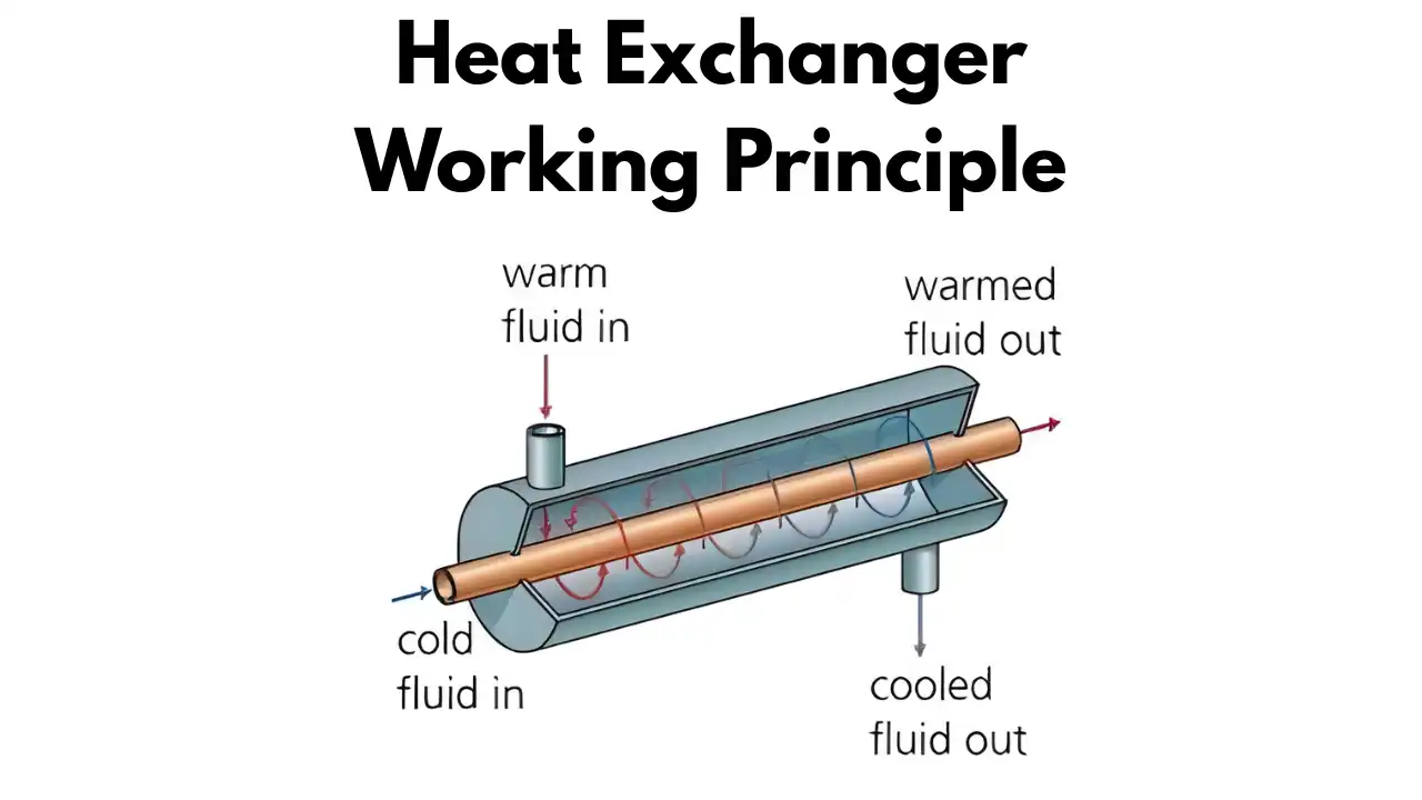
Bottom Line: If your process involves clean-to-moderately fouling fluids, moderate pressure and temperature ranges, and space is at a premium, a plate heat exchanger is usually the better choice. If your application demands extreme pressure, very high temperatures, or handling of heavily fouling or particulate fluids, a shell and tube heat exchanger remains the more reliable option.
Final Thoughts
The plate heat exchanger has earned its place as one of the most efficient and space-saving thermal transfer technologies available today. From gasketed and brazed designs to wide-gap and double-wall variants, understanding the different plate heat exchanger types — along with their working principle, components, and ideal applications — makes it much easier to select the right unit for your specific process needs.
Whether you’re upgrading an HVAC system, optimizing a food processing line, or comparing options against a shell and tube heat exchanger, the compact footprint and high thermal efficiency of plate heat exchangers make them worth serious consideration for most low-to-medium pressure applications.
For a broader overview of heat exchanger technology as a whole, check out our complete guide: Heat Exchangers: Types, Working, and Applications →