Ask ten plant engineers what a heat exchanger does and you’ll get ten slightly different answers, but they’ll all circle back to the same idea moving heat from one fluid to another without letting the two ever touch. It sounds almost too simple for how much industry depends on it. At Mechstera, we’ve spent years around these units on shop floors and job sites, and the honest truth is that most failures we get called out for aren’t design flaws they’re a poor match between the exchanger and the process it’s bolted onto.
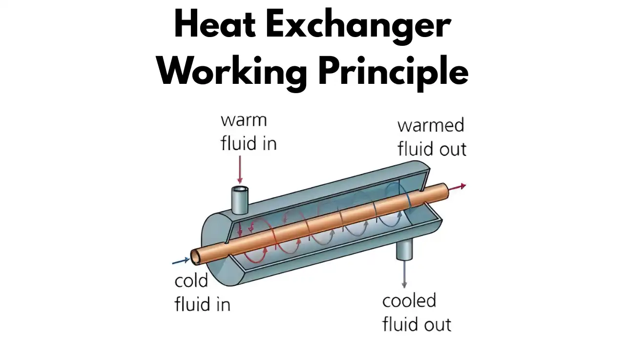
The heat exchanger working principle itself isn’t complicated once you strip away the jargon. Two fluids at different temperatures pass close to each other, separated by a conductive wall usually metal and heat naturally moves from the hotter fluid to the cooler one until they get closer to equilibrium. That’s conduction doing the work across the wall, with convection carrying the heat through the moving fluids on either side. No mixing, no contamination, just energy quietly changing hands.
Why the Heat Exchanger Working Principle Matters More Than People Think
Here’s the thing nobody notices a heat exchanger until it stops doing its job. Your car’s radiator, your home boiler, the condenser behind your fridge, the massive shell units cooling a power plant’s turbine they’re all leaning on this same basic transfer of thermal energy. Once you understand the working principle, you start seeing heat exchangers everywhere, and you also start understanding why a badly specified one causes so much downstream grief: overheating, energy waste, or in worse cases, safety incidents.
We tell clients this often the exchanger isn’t just a component, it’s the safety valve for the whole thermal system. Get it wrong, and everything downstream inherits the problem.
Heat Exchanger Working Principle With Diagram: The Flow Arrangements
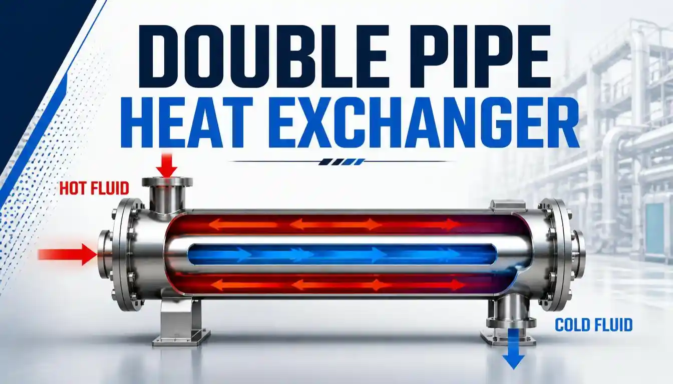
If you’ve ever looked at a heat exchanger working principle diagram, you’ll notice the fluid paths are drawn a certain way for a reason the direction fluids travel relative to each other changes how efficiently heat moves.
In a parallel flow setup, both fluids enter from the same end and travel in the same direction. It’s the easiest to visualize, but it’s also the least efficient, because the temperature difference between the two fluids shrinks fast as they travel down the length of the unit.
Counter flow flips that the fluids move in opposite directions. This keeps a more consistent temperature gradient across the entire length, which is why counterflow designs are generally the go to when you need maximum heat recovery. We default to counter flow arrangements unless there’s a specific reason not to, and in practice, that’s most of the time.
Cross flow sits in the middle, with fluids moving perpendicular to each other. It’s common where space or piping constraints make parallel or counter flow arrangements awkward automotive radiators are a familiar example.
| Flow Arrangement | How It Works | Typical Efficiency | Common Use |
|---|---|---|---|
| Parallel Flow | Fluids enter same end, travel same direction | Lowest | Simple, low cost cooling tasks |
| Counter Flow | Fluids move in opposite directions | Highest | Industrial heat recovery, process cooling |
| Cross Flow | Fluids move perpendicular to each other | Moderate | Radiators, HVAC coils, compact systems |
Common Types Built Around the Same Principle
Every type of heat exchanger applies that same core principle differently, depending on what the process actually needs.
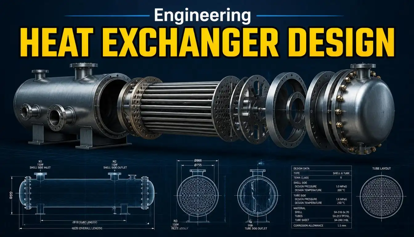
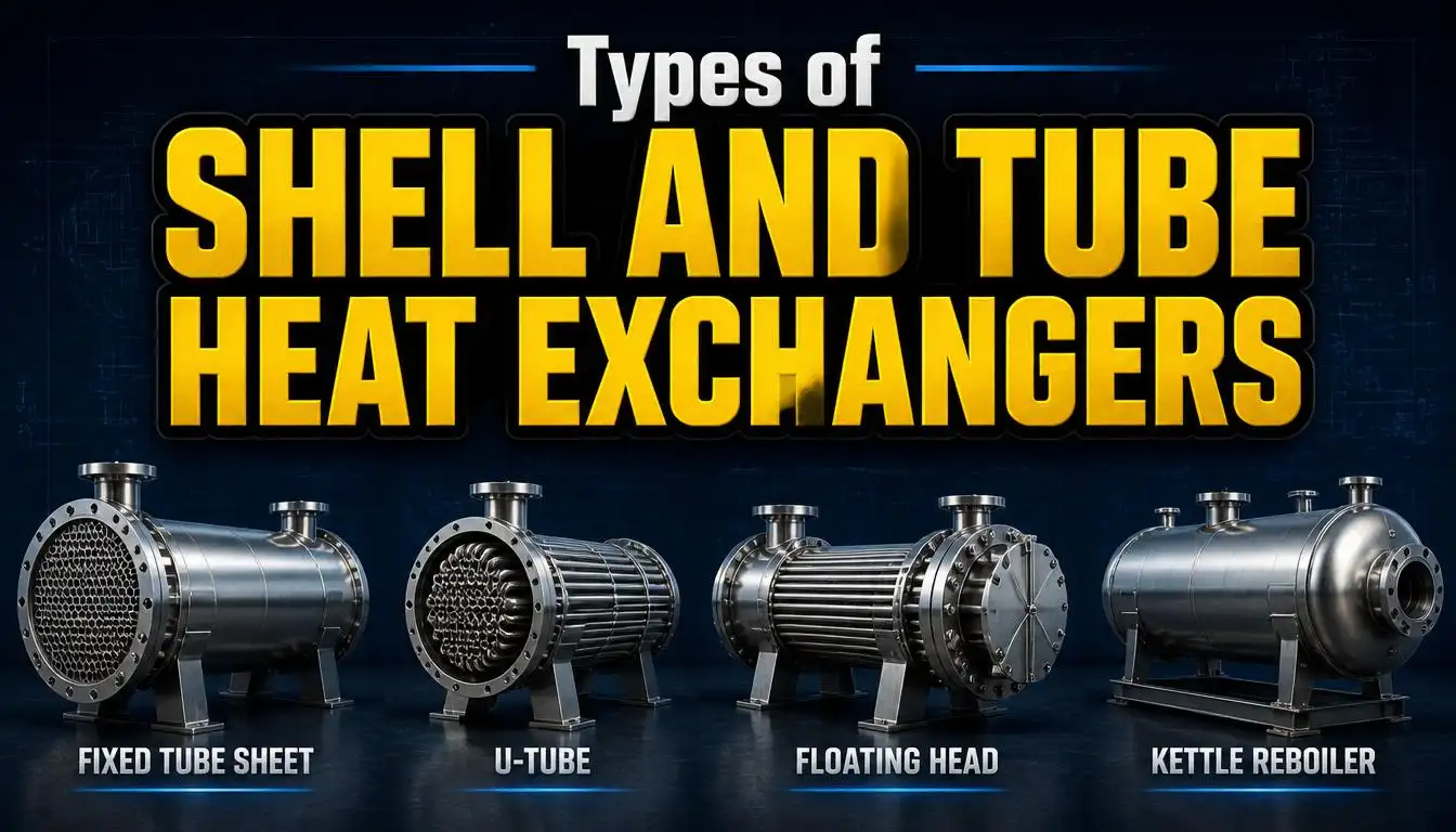
Shell and tube units are probably the most recognizable one fluid runs through a bundle of tubes, while the second flows around them inside an outer shell. They’re rugged, easy to service, and still the workhorse of refineries and power plants decades after the design was standardized.
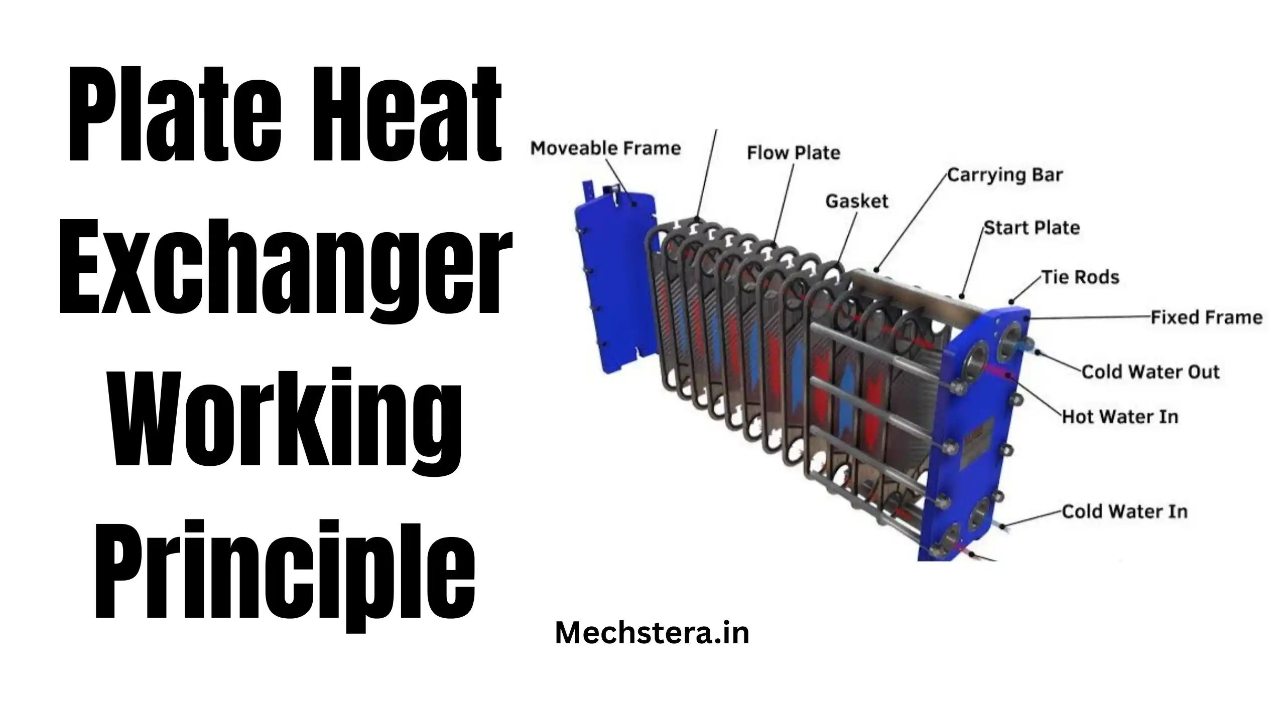
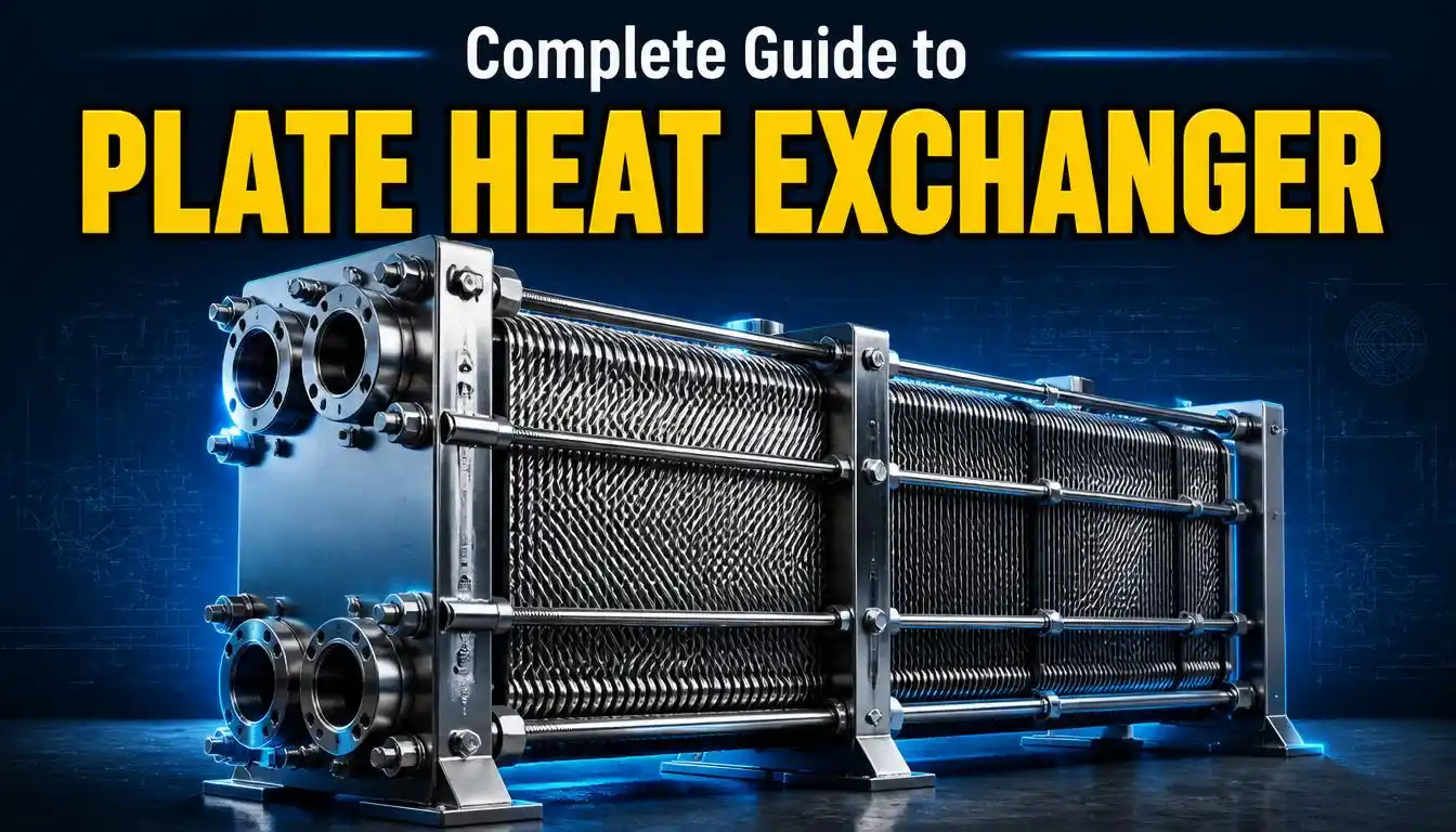
Plate heat exchangers stack thin corrugated plates instead, forcing fluid through narrow channels. The corrugation creates turbulence, which honestly is the whole trick turbulent flow transfers heat far better than fluid gliding by smoothly, and it lets a plate unit do the same job as a much bigger shell and tube in a fraction of the footprint. That’s part of why the heat exchanger working principle in HVAC applications increasingly leans on plate designs building mechanical rooms don’t have room to spare.
Finned tube exchangers add fins to the tube surface to increase the contact area a fix that matters a lot when one side of the exchange is air, which conducts heat poorly compared to liquids. You’ll find these in gas coolers and air handling units.
Air cooled exchangers skip a second liquid altogether, relying on fans (or sometimes just airflow) to pull heat away useful anywhere water access is limited.
| Type | Pros | Cons |
|---|---|---|
| Shell and Tube | Durable, handles high pressure/temperature, easy to repair | Bulkier, higher material cost |
| Plate | Compact, high efficiency, easy to expand or clean | Gaskets limit max pressure/temperature |
| Finned Tube | Great for low conductivity fluids like air | Fins can trap debris, need regular cleaning |
| Air Cooled | No water source needed, lower maintenance | Less efficient in high ambient heat |
Heat Exchanger Working Principle in HVAC Systems
Inside an HVAC setup, the exchanger is doing quiet, constant work pulling heat out of return air in summer, or pushing it back in during winter, all without mixing conditioned air with refrigerant or boiler water. Coils in an air handler are really just finned tube exchangers dressed for the job. Anyone who’s swapped out a corroded HVAC coil knows how much performance drops the moment fin surface area gets fouled that’s the working principle failing in slow motion, not all at once.
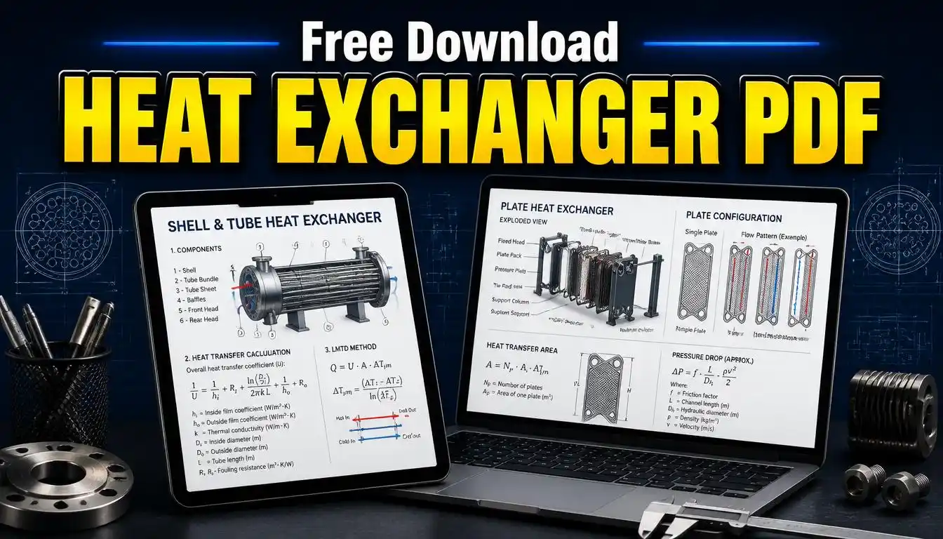
A lot of facility managers searching for heat exchanger working principle PDF resources are usually chasing spec sheets for exactly this reason they want to match replacement coils correctly rather than guess. It’s a reasonable instinct, though we’d argue the diagram matters less than understanding what the coil is actually doing in your specific airflow and refrigerant loop.
Meanwhile, you can also check out our guide on : Shell and Tube Heat Exchanger: Working, Diagram, Types & Uses
Materials and Design Choices That Shape Performance
Picking the right material isn’t a footnote it’s half the design decision. Copper and steel dominate because they conduct heat well and hold up structurally, but they’re not bulletproof against every fluid. Seawater, acids, and aggressive chemical streams eat through standard metals fast, which is why titanium or specialized polymers show up in marine and chemical processing units despite costing more upfront. Buyers chasing the lowest upfront price on materials usually regret it within a couple of maintenance cycles we’ve replaced enough prematurely corroded units to say that with confidence.
Flow rate, fluid temperature, and the acceptable pressure drop across the unit all feed into sizing, too. None of this is exotic engineering, but it does require actually knowing your process conditions rather than picking a catalog part that “looks about right.”
For readers who want a deeper technical breakdown of overall heat transfer coefficients, fouling, and field performance checks, Turn2Engineering’s guide on how heat exchanger performance is affected by flow distribution, fouling, and fin condition in real operating conditions is a solid technical reference worth reading alongside this piece. LineCAD
Installation, Maintenance, and Repair Realities
Installation complexity depends heavily on scale. A fridge’s exchanger gets built in at the factory; an industrial shell-and-tube unit needs proper alignment, supports, and commissioning checks by someone who’s done it before. Skipping that step is how you end up with vibration issues six months down the line.
Maintenance is where design decisions from years earlier come back around. If accessibility wasn’t considered up front, routine cleaning turns into a half-day teardown instead of a quick service call. Fouling, scaling, and fin blockage are the usual suspects behind declining performance, and catching them early is far cheaper than reactive repairs.
Most units can be repaired rather than replaced if the damage is limited to a section of tubes or a few gaskets. Full replacement only really makes sense when corrosion has spread structurally or when the unit’s simply outdated relative to current process demands.
Wrapping Up
The heat exchanger working principle hasn’t changed much in over a century move heat from hot to cold, keep the fluids apart, and let conduction and convection do the rest. What has changed is how precisely we can now match a design to a process, whether that’s a compact plate unit tucked into an HVAC mechanical room or a shell-and-tube monster cooling a refinery stream. At Mechstera, we still find the biggest performance gains come not from exotic materials, but from getting the fundamentals flow arrangement, surface area, and material choice right the first time.
FAQs
What is the basic working principle of a heat exchanger?
Heat moves from a hotter fluid to a cooler one across a conductive surface, without the two fluids mixing directly.
Which flow arrangement is most efficient parallel, counter, or cross flow?
Counter flow generally delivers the best efficiency because it maintains a more consistent temperature difference along the entire length of the exchanger.
Where are heat exchangers used in HVAC systems?
They’re used in air handler coils, boilers, chillers, and condensers to transfer heat between refrigerant, water, and air without contamination.
Can a damaged heat exchanger be repaired instead of replaced?
In most cases, yes especially when damage is isolated to specific tubes, plates, or gaskets rather than widespread structural corrosion.
What materials are commonly used in heat exchanger construction?
Copper and steel are most common, with titanium or engineered polymers used for corrosive fluids like seawater or certain chemicals.