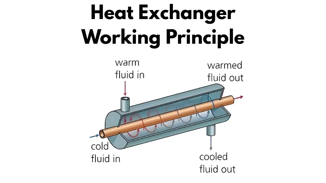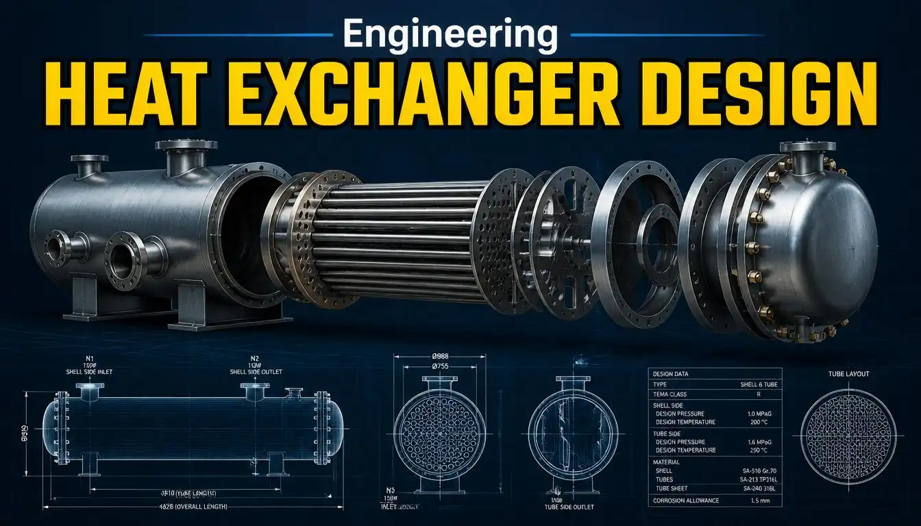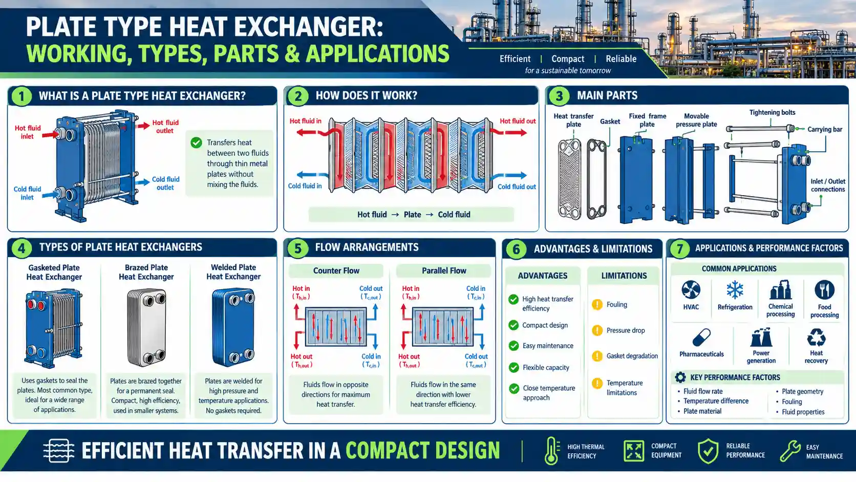
Shell and tube heat exchangers are among the most widely used heat transfer equipment in process industries, power plants, refineries, and HVAC systems. While the basic principle — transferring heat between two fluids through a bundle of tubes enclosed in a shell — remains the same across designs, the internal construction can vary significantly depending on the application, pressure, temperature, and maintenance requirements.
Understanding the different shell and tube heat exchanger types is essential for engineers, procurement teams, and plant operators who need to select equipment that balances performance, cost, and serviceability. In this guide, we’ll break down the major classifications, explain how each design works, and help you decide which type best suits your process needs.
If you haven’t already, check out our detailed pillar guide on Shell and Tube Heat Exchangers to understand the fundamentals before diving into the type-specific breakdown below.
Classification of Shell and Tube Heat Exchangers
According to the Tubular Exchanger Manufacturers Association (TEMA), shell and tube heat exchangers are broadly classified based on how the tube bundle is constructed and how it interacts with the shell. The classification largely depends on:
- Whether the tube bundle is removable or fixed
- How thermal expansion is accommodated
- The number of shell and tube passes
- Ease of cleaning and maintenance
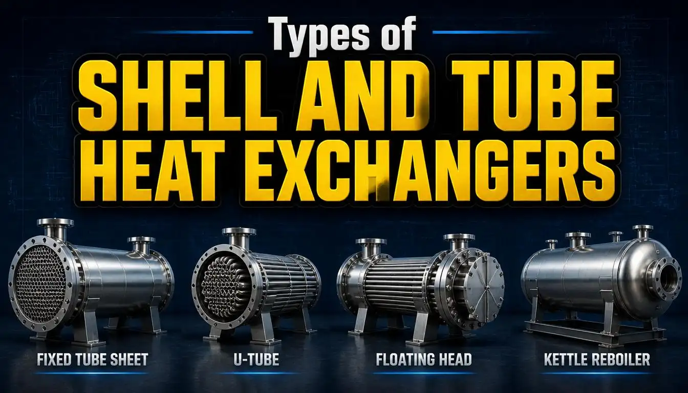
The four primary types of shell and tube heat exchangers are:
- Fixed Tube Sheet Heat Exchanger
- U-Tube Heat Exchanger
- Floating Head Heat Exchanger
- Multi-pass configurations (1-2 and 2-4 designs)
Each of these serves a distinct purpose depending on operating conditions like fouling tendency, temperature differential, and cleaning frequency. Let’s look at each one in detail.
Fixed Tube Sheet Heat Exchanger
A fixed tube heat exchanger is the simplest and most economical shell and tube design. In this configuration, the tube sheets are welded directly to the shell at both ends, meaning the tube bundle cannot be removed for external cleaning.
Key characteristics:
- Tubes are fixed rigidly on both ends
- Lower cost compared to removable-bundle designs
- Simple construction with fewer components
- Limited ability to accommodate thermal expansion differences between shell and tubes
Because the tube bundle is permanently fixed, this design is best suited for applications where the shell-side fluid is clean (non-fouling) since only the tube side can be mechanically cleaned. When large temperature differentials exist between the shell and tubes, an expansion joint is often added to the shell to relieve thermal stress — a detail covered well in Engineering Toolbox’s overview of heat exchanger types.
Best for: Clean shell-side fluids, lower budgets, and applications where thermal expansion differences are minimal.
U-Tube Heat Exchanger
The U-tube heat exchanger is one of the most popular designs due to its flexibility and ease of maintenance. As the name suggests, each tube is bent into a “U” shape, with both ends fixed to the same tube sheet.
Advantages of the U tube heat exchanger design:
- The tube bundle can be removed from the shell for cleaning
- Only one tube sheet is required, reducing material and fabrication cost
- The U-bend naturally accommodates thermal expansion, eliminating the need for expansion joints
- Ideal for high-pressure and high-temperature-differential applications
However, u tube heat exchangers do have a drawback: the bent sections are difficult to clean mechanically using standard rodding or brushing tools, making them less suitable when the tube-side fluid is prone to heavy fouling. Chemical cleaning is typically used instead.
This is why the shell and tube heat exchanger u tube configuration is commonly found in boiler feedwater heaters, steam generators, and other applications where the tube-side fluid is relatively clean but pressure and temperature swings are significant. A helpful visual breakdown of U-tube bundle construction can be found on Wikipedia’s Shell and Tube Heat Exchanger page.
Best for: High-pressure/high-temperature applications, clean tube-side fluids, and situations requiring thermal expansion flexibility without added mechanical complexity.
Floating Head Heat Exchanger
The floating head design solves the biggest limitation of the fixed tube sheet exchanger: the inability to remove the tube bundle. In this configuration, one tube sheet is fixed to the shell, while the other “floats” freely, allowing the entire tube bundle to be withdrawn for cleaning and inspection.
Key features:
- Tube bundle is fully removable from both the shell side and tube side
- Accommodates differential thermal expansion between shell and tubes without stress
- Ideal for services where both shell-side and tube-side fluids are prone to fouling
- More complex and expensive than fixed tube sheet or U-tube designs due to additional floating head cover and packing/seal arrangements
Floating head exchangers are widely used in refineries and petrochemical plants where frequent cleaning is mandatory due to heavy fouling fluids like crude oil, slurries, or heavy hydrocarbons. The American Institute of Chemical Engineers (AIChE) has published multiple technical papers discussing floating head design considerations for fouling-prone services.
Best for: Heavy fouling on both shell and tube sides, applications requiring frequent mechanical cleaning, and high thermal cycling conditions.
1–2 Shell and Tube Heat Exchanger
A 1-2 shell and tube heat exchanger refers to a configuration with one shell pass and two tube passes. This means the shell-side fluid flows through the shell once, while the tube-side fluid makes two passes — flowing in one direction through half the tubes, then reversing direction through the other half via a pass partition plate in the header.
Why use a 1-2 configuration?
- Increases tube-side fluid velocity, improving heat transfer coefficients
- Reduces the number of tubes needed for a given flow rate compared to single-pass designs
- Commonly used when a compact, cost-effective design is needed with moderate performance requirements
The 1 2 shell and tube heat exchanger design is one of the most common configurations in industrial use because it strikes a practical balance between thermal performance, pressure drop, and fabrication simplicity. Since it involves a temperature cross situation in certain configurations, care must be taken with LMTD correction factors — a topic well explained in ScienceDirect’s heat exchanger design resources.
2–4 Shell and Tube Heat Exchanger
When higher thermal effectiveness is required, engineers often move to a 2-4 shell and tube heat exchanger configuration — two shell passes and four tube passes. Multiple shell passes are usually achieved by adding a longitudinal baffle inside the shell, effectively splitting it into two separate flow zones.
Benefits of the 2-4 design:
- Closer approximation to true counter-current flow, improving thermal efficiency
- Better suited for applications with a close temperature approach or a temperature cross
- Allows for higher heat duty within a single shell compared to 1-2 designs
The trade-off is increased mechanical complexity and cost due to the longitudinal baffle and additional tube passes. This configuration is typically reserved for applications where a 1-2 exchanger cannot meet the required thermal performance due to LMTD correction factor limitations, as outlined in Chemical Engineering World’s technical resources.
Which Type is Best? Selection Guide
Choosing the right shell and tube heat exchanger type depends on several operating and economic factors. Here’s a quick comparison to guide your decision:
| Factor | Fixed Tube Sheet | U-Tube | Floating Head | 1-2 Pass | 2-4 Pass |
|---|---|---|---|---|---|
| Cost | Lowest | Low-Moderate | Highest | Moderate | Moderate-High |
| Cleanability (shell side) | Poor | Poor | Excellent | Depends on shell type | Depends on shell type |
| Cleanability (tube side) | Good | Fair (bends limit access) | Excellent | Good | Good |
| Thermal expansion handling | Limited (needs expansion joint) | Excellent | Excellent | Depends on base design | Depends on base design |
| Fouling tolerance | Low | Moderate | High | Moderate | Moderate-High |
| Thermal performance | Standard | Standard | Standard | Good | Better (closer to counter-flow) |
General selection guidelines:
- Choose Fixed Tube Sheet when both fluids are clean, budget is tight, and thermal expansion differentials are minor.
- Choose U-Tube when tube-side fluid is clean, but high pressure/temperature swings require expansion flexibility.
- Choose Floating Head when both shell-side and tube-side fluids foul easily and require regular mechanical cleaning.
- Choose 1-2 Pass for standard industrial applications needing a balance of cost and performance.
- Choose 2-4 Pass when higher thermal efficiency is needed and a temperature cross exists that a single-pass design can’t handle.
For further engineering reference on selection criteria, the HTRI (Heat Transfer Research, Inc.) provides industry-standard design and rating tools used by process engineers worldwide to validate exchanger selection.
Final Thoughts
Selecting the right shell and tube heat exchanger type isn’t just about upfront cost — it’s about matching the design to your fluid properties, fouling tendencies, maintenance capabilities, and thermal performance requirements. A fixed tube sheet exchanger might save money initially, but a floating head design could save far more in downtime and cleaning costs over the equipment’s lifetime.
Before finalizing your choice, it’s worth consulting with a heat exchanger manufacturer or process engineer who can run detailed thermal and mechanical calculations specific to your application.
Want to understand the broader fundamentals first? Head back to our comprehensive guide on Shell and Tube Heat Exchangers to explore construction, working principles, and applications in more depth.